
Owner manual

Publication GMSI10-UM001C-EN-E - June 2011
Installing the XM-720 Machine Monitor 21
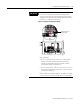
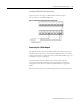
IMPORTANT
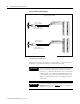
By default, both buffered outputs have been wired for a
positive bias transducer (accelerometer and powered
sensor). This means that orange jumper wires have been
supplied on the XM-120/121/122 terminal block between
terminals 5, 6, and 22 (see Figure 2.9).
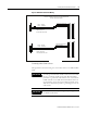
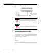
Figure 2.9 Jumpers for buffer input wiring
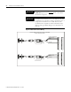
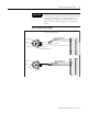
If the transducer is not a positive bias transducer, follow
these guidelines:
• For a non-contact sensor, remove the orange jumper
between terminals 5 and 6 (terminals 22 and 6 for
channel 2) and install it between terminals 5 and 21
(terminals 22 and 21 for channel 2).
• For a non-bias sensor, such as a velocity sensor, remove
the orange jumper between terminals 5 and 6 (terminals
22 and 6 for channel 2).
Refer to Table 2.3 for details. Refer to the XM Users Guide
for more information about the XM-120/121/122 module.
123456789100
16 17 1819 2021 22 23 24 25 2627 2829 3031 3233
34 35 3637 3839 4041 4243 4445 4647 48 49 50 51
11 12 1314 15 123456789100
1617 18 19 2021 222324 25 2627 28 2930 31 3233
3435 36 373839 40 4142 4344 45 4647 48 4950 51
1112 13 1415
123456789100
16 1718 19 20 2122 23 2425 26 2728 2930 31 3233
3435 36 3738 39 4041 42 4344 45 4647 48 495
1112 13 1415
Orange jumpers for
buffer outputs