
Owner manual

Publication GMSI10-UM001C-EN-E - June 2011
Installing the XM-720 Machine Monitor 15
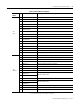
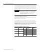
Table 2.2 Terminal Block Assignments
1 It is assumed that the relay is to be configured as failsafe.
2. It is assumed that the relay is to be configure as non-failsafe.
Terminal
Block
No. Name Description
TB1
(top)
E AC Earth Ground AC equipment earth ground
L AC Input Line AC power (hot)
N AC Input Neutral AC common (neutral)
4
Fault Relay NC
1
Normally Closed contact for Module/Transducer Fault relay
5 Fault Relay Common Common for Module/Transducer Fault relay
6
Fault Relay NO
1
Normally Open contact for Module/Transducer Fault relay
7
Warning Relay NO
2
Normally Open contact for Warning relay
8 Warning Relay Common Common for Warning relay
9
Warning Relay NC
2
Normally Closed contact for Warning relay
10
Trip Relay NO
2
Normally Open contact for Trip relay
11 Trip Relay Common Common for Trip relay
12
Trip Relay NC
2
Normally Closed contact for Trip relay
13 Reset Relay Switch Switch input to reset internal relays
14 Switch RTN Switch return for Reset Relay and Setpoint Multiplier switch
15 Setpoint Multiplier Switch Switch input to activate Setpoint Multiplication (active open)
16 24V Common Tachometer 24V power return
TB2
(bottom)
17 Xducer 1 (+) Vibration transducer channel 1 connection
18 Xducer 1 (-) Vibration transducer channel 1 connection
19 Chassis GND Connection to chassis ground (channel 1 shield)
20 Xducer 2 (+) Vibration transducer channel 2 connection
21 Xducer 2 (-) Vibration transducer channel 2 connection
22 Chassis GND Connection to chassis ground (channel 2 shield)
23 Xducer +24V Transducer power, positive side; used to power external sensor
24 Xducer -24V Transducer power, negative side; used to power external sensor
25
4-20mA 1 (+)
3
4-20mA output; channel 1
250 ohm maximum load
26
4-20mA 1 (-)
3
27 Chassis GND Connection to chassis ground (4-20mA outputs shield)
28
4-20mA 2 (+)
3
4-20mA output; channel 2
250 ohm maximum load
29
4-20mA 2 (-)
3
30 Tachometer In (+) Tachometer transducer/signal input, positive side
31 Tachometer In (-) Tachometer transducer/signal input, negative side
32 Chassis GND Connection to chassis ground (tachometer shield)