
Owner manual

Publication GMSI10-UM001C-EN-E - June 2011
12 Installing the XM-720 Machine Monitor
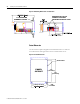
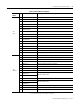
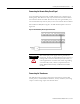
Figure 2.1 Mounting Dimensions and Side View
Cutout Dimension
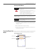
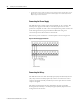
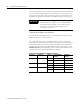
Use the full size template shipped with the XM-720 monitor to mark the
cutout dimensions. The figure below shows a reduced scale cutout.
Figure 2.2 Cutout Dimensions
1234
5
6
7
89100
1617 1819 2021 22 2324 252627 2829 303132 33
3435 363738 394041 424344 454647 484950 51
1112 13 14 15 1234
5
6
7
89100
1617 1819 2021 22 2324 252627 282930 3132 33
3435 363738 394041 424344 454647 484950 51
1112 13 14 15
1/4" MOUNTING
SCREWS 4 PLACES
KNOCKOUTS FOR 3/4"
CONDUIT FITTINGS
LOCATED IN TOP OF CASE.
FRONT PANEL
PANEL
CUTOUT
7.25
[184.15mm]
7.75
[196.85mm]
4.650 [118.11mm]
Ø.26
4 PLACES