User Manual XM-720 Machine Monitor Catalog Numbers 1440-PK02-05M0, 1440-PK02-05M1, 1440-PK02-05M2
Important User Information Solid-state equipment has operational characteristics differing from those of electromechanical equipment. Safety Guidelines for the Application, Installation and Maintenance of Solid State Controls (publication SGI-1.1 available from your local Rockwell Automation sales office or online at http://www.rockwellautomation.com/literature/) describes some important differences between solid-state equipment and hard-wired electromechanical devices.
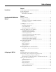
Table of Contents Chapter 1 Introduction Introducing the XM-720 Machine Monitor . . . . . . . . . . . . . . . . . . . . . . 5 System Description . . . . . . . . . . . . . . . . . . . . . . . . . . . . . . . . . . . . . . . . . 6 Using this Manual. . . . . . . . . . . . . . . . . . . . . . . . . . . . . . . . . . . . . . . . . . . 7 Document Conventions . . . . . . . . . . . . . . . . . . . . . . . . . . . . . . . . . . 7 Chapter 2 Installing the XM-720 Machine Monitor Package Contents . . . . . . . . . .
Table of Contents 4 Appendix A Specifications . . . . . . . . . . . . . . . . . . . . . . . . . . . . . . . . . . . . . . . . . . . . . . . . . . . . . . . . . 53 Appendix B Comparing Connections Between Power Supply & Relay Connections . . . . . . . . . . . . . . . . . . . . . . . . . . . 57 Signal Conditioner Connections . . . . . . . . . . . . . . . . . . . . . . . . . . . . . . 58 the 5802 and the XM-720 Glossary . . . . . . . . . . . . . . . . . . . . . . . . . . . . . . . . . . . . . . . . . . .
Chapter 1 Introduction This chapter provides an overview of the XM-720 Machine Monitor. It also discusses the components of the monitor. For information about See page Introducing the XM-720 Machine Monitor 5 System Description 6 Using this Manual 7 The XM-720 Machine Monitor is referred to as XM-720 or monitor throughout this manual.
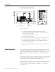
Introduction Figure 1.
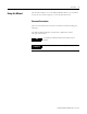
Introduction Using this Manual 7 This manual introduces you to the XM-720 Machine Monitor. It is intended for anyone who installs, configures, or uses the XM-720 monitor. Document Conventions There are several document conventions used in this manual, including the following: The XM-720 Machine Monitor is referred to as XM-720 or monitor throughout this manual. TIP EXAMPLE A tip indicates additional information which may be helpful. This convention presents an example.
Introduction Publication GMSI10-UM001C-EN-E - June 2011
Chapter 2 Installing the XM-720 Machine Monitor This chapter discusses how to install and wire the XM-720 monitor. It also describes the front panel of the monitor.
Installing the XM-720 Machine Monitor Package Contents The XM-720 monitor is shipped with the following items: • Monitor Table 2.1 XM-720 Monitor Cat. No.
Installing the XM-720 Machine Monitor 11 Hazardous Locations Due to the proximity of some control rooms to process machinery, the control room interior may be designated as a hazardous area within the definition of Article 500 of the (U.S.) National Electrical Code, or similar codes in other countries. If the control room is classified as a Division 2 area (N.E.C.
Installing the XM-720 Machine Monitor Figure 2.1 Mounting Dimensions and Side View KNOCKOUTS FOR 3/4" CONDUIT FITTINGS LOCATED IN TOP OF CASE.
Installing the XM-720 Machine Monitor 13 Mounting the XM-720 Monitor ATTENTION • Disconnect all electrical power from the panel before making cutout. • Make sure area around the panel cutout is clear. • Take precautions so that metal cuttings do not enter any components already installed in panel • Failure to follow this warning may result in personal injury or damage to the panel components. Mount the monitor to the panel using four 1/4 inch mounting screws (not included in shipment).
Installing the XM-720 Machine Monitor The XM-720 terminal blocks have spring clamp connectors. Follow these steps to connect wiring to the back panel connectors. IMPORTANT The XM-720 terminal plugs are keyed so they will only fit into the corresponding socket. Be certain that you are connecting the wires to the correct connectors. 1. Insert a 1/8" [3.5 mm] wide blade-type screwdriver into the slot above the selected wiring port. 2.
Installing the XM-720 Machine Monitor 15 Table 2.2 Terminal Block Assignments Terminal Block TB1 (top) TB2 (bottom) No.
Installing the XM-720 Machine Monitor 3 4-20mA operation requires a jumper at terminals 25 & 26 (or terminals 28 & 29) if 4-20mA output is not used. Otherwise the associated meter on front panel will not function properly. Refer to Connecting the 4-20mA Outputs on page 29 for more information. Connecting the Power Supply The XM-720 monitor accepts inputs from 100-240V ac (47 to 63 Hz). The internal power supply has internal (not accessible) input fuse. No other protection is required.
Installing the XM-720 Machine Monitor 17 The XM-720 back panel terminal block is equipped with three single-pole, double-throw relays. Figures 2.5 to 2.7 show the connection for the three relays. Module/Transducer Fault Relay In the provided configuration files, the Fault relay is configured to be a failsafe relay and is set up to activate if any one of the conditions occurs: • There is a hardware or firmware failure. • A transducer fault is detected on the associated transducer.
Installing the XM-720 Machine Monitor Figure 2.6 Wiring Connection for Warning Relay (Non-failsafe) Trip Relay In the provided configuration files, the Trip relay is configured to activate when the overall measurement in either channel exceeds the danger threshold level (same conditions that activate the Trip LED). This relay is also configured as a non-failsafe relay. Figure 2.7 shows the on-board relay connection for the Trip relay.
Installing the XM-720 Machine Monitor 19 Connecting the Remote Relay Reset Signal In the provided configuration files, the XM-720 relays are configured to be latching relays. This means the relays stay activated even when the condition that caused the alarm has ended. The remote relay reset signal enables you to reset the XM-720 relays remotely after you have corrected the alarm condition. Wire the Remote Relay Reset Signal to the XM-720 back panel as shown in Figure 2.8. Figure 2.
Installing the XM-720 Machine Monitor The sensitivity, operating range, and power requirements have been predefined in the provided configuration files. The characteristics of the transducer and the signal processing performed on the input signals can be changed using the XM Serial Configuration Utility. Refer to Transducer Parameters on page 44. IMPORTANT The 1440-PK02-05M2 (gSE) monitor can measure both "standard" vibration, similarly to the 1440-PK02-05M0, and g’s Spike Energy™ (gSE).
Installing the XM-720 Machine Monitor IMPORTANT 21 By default, both buffered outputs have been wired for a positive bias transducer (accelerometer and powered sensor). This means that orange jumper wires have been supplied on the XM-120/121/122 terminal block between terminals 5, 6, and 22 (see Figure 2.9). Figure 2.
Installing the XM-720 Machine Monitor Connecting an IEPE Accelerometer The following figure shows the wiring of an IEPE accelerometer to the XM-720 back panel. IMPORTANT IMPORTANT IMPORTANT IMPORTANT Publication GMSI10-UM001C-EN-E - June 2011 You may ground the cable shield at either end of the cable. Do not ground the shield at both ends. Recommended practice is to ground the cable shield to one of the Chassis GND terminals on the XM-720 terminal block and not at the transducer.
Installing the XM-720 Machine Monitor 23 Figure 2.10 IEPE Accelerometer Wiring TYPICAL WIRING FOR IEPE ACCELEROMETER TO XM-720 BACK PANEL Pin A - Signal Pin B - Common Channel 1 Input Signal Signal Common Shield 17 18 19 Cable shield not connected at this end Pin A - Signal Pin B - Common Channel 2 Input Signal Signal Common Shield 20 21 22 Cable shield not connected at this end Connecting a Non-Contact Sensor The figure below show the wiring of a non-contact sensor to the XM-720 back panel.
Installing the XM-720 Machine Monitor IMPORTANT IMPORTANT Using the XM Serial Configuration Utility, make certain the IEPE Power parameter is disabled. Refer to Transducer Parameters on page 44. A jumper from terminal 5 to 21 on the XM-120/121/122 terminal block is required for channel 1 buffered output. A jumper from terminal 22 to 21 on XM-120/121/122 terminal block is required for channel 2 buffered output. Refer to Setting the Buffer Range for the Transducer on page 20. Figure 2.
Installing the XM-720 Machine Monitor 25 Connecting a Passive Transducer The figure below shows the wiring of a passive transducer, such as a coil-based velocity sensor, to the XM-720 back panel. IMPORTANT IMPORTANT IMPORTANT IMPORTANT You may ground the cable shield at either end of the cable. Do not ground the shield at both ends. Recommended practice is to ground the cable shield to one of the Chassis GND terminals on the XM-720 terminal block and not at the transducer.
Installing the XM-720 Machine Monitor Figure 2.
Installing the XM-720 Machine Monitor IMPORTANT 27 A jumper from terminal 5 to 6 on the XM-120/121/122 terminal block is required for channel 1 buffered output. A jumper from terminal 22 to 6 on XM-120/121/122 terminal block is required for channel 2 buffered output. Refer to Setting the Buffer Range for the Transducer on page 20. Figure 2.
Installing the XM-720 Machine Monitor Connecting the Tachometer Signal The XM-720 monitor provides a single tachometer input signal. The signal processing performed on the tachometer signal depends on the configuration of the module. See the XM Module User Guide for a description of the tachometer parameters. IMPORTANT The tachometer measurement has been disabled in the provided configuration files.
Installing the XM-720 Machine Monitor 29 Connecting a Hall Effect Tachometer Sensor Figure 2.15 shows the wiring of a Hall Effect Tachometer Sensor, Cat. No. 44393, to the XM-720 back panel. Figure 2.15 Hall Effect Tachometer Signal Connection Connecting the 4-20mA Outputs The XM-720 monitor includes an isolated 4-20mA per channel output into a maximum load of 250 ohms.
Installing the XM-720 Machine Monitor Figure 2.16 4-20mA Output Connections Channel 2 4-20mA output is not being used. Therefore a jumper from terminal 28 to 29 is required. ATTENTION ATTENTION The 4-20mA outputs must be grounded at a single point. Connect the 4-20mA Return signal to chassis ground at the XM-720 end through the 4-20mA (-) terminal. Do not ground the 4-20mA return elsewhere.
Installing the XM-720 Machine Monitor 31 Figure 2.17 Setpoint Multiplication Connection ATTENTION Front Panel Description The switch input power supply must be grounded at a single point. Connect the Switch Return signal to chassis or earth ground at either the XM-720 system, the switch, or other equipment that is wired to this switch. If grounding at the XM-720 system, place a jumper between the Switch RTN terminal and any available Chassis GND terminal.
Installing the XM-720 Machine Monitor Bargraph Meters The XM-720 front panel has two vertical-scale meters, one for each input channel. Each meter consists of 31 solid-state lamps (light emitting diodes) arranged one above the other. Scale markings on the window appear at 3% increments, thus there is one scale mark for each of the thirty lamps. In the provided configuration files, each meter is configured to continuously display the overall vibration level.
Installing the XM-720 Machine Monitor 33 To determine the signal amplitude on bargraph meter To determine the signal amplitude in engineering units, use the following formula: Amplitude = ( Bargraph % ⁄ 100 ) × ( 4-20mA Max Range value – 4-20mA Min Range value ) + 4-20mA Min Range value EXAMPLE meter reading: 40% 4-20mA Min Range value: 0 mils 4-20mA Max Range value: 5 mils amplitude = (40% / 100) x (5 -0) + 0 = 2 mils To determine placement for Alert and Danger Threshold Arrows The caption sheet (inc
Installing the XM-720 Machine Monitor BNC Connectors The XM-720 front panel provides three BNC connectors directly below the bargraph meters. There are two connectors (CH1 and CH2) for monitoring the input signals. And a third BNC connector (TACHO) for phase referencing or triggering. WARNING EXPLOSION HAZARD Do not use BNC connectors when area is known to be hazardous. BNC caps must be securely installed on ALL connectors during normal operation.
Installing the XM-720 Machine Monitor 35 Table 2.D LED Description LED State Indicates Module Fault Off Normal condition On • A hardware or firmware failure is preventing proper operation of the device. • Relay #1 is not configured to be failsafe. Typically this occurs on new installations, in which the XM-720 has not been configured. Refer to Chapter 3 on page 37 for information on how to configure the XM-720.
Installing the XM-720 Machine Monitor To remove the XM-720 terminal blocks, grasp the terminal block with your thumb and forefinger and pull straight out. Inserting the XM-720 Terminal Blocks WARNING When you connect or disconnect the RTB with field side power, an electrical arc can occur. This could cause an explosion in hazardous location installations. Be sure that power is removed or the area is nonhazardous before proceeding.
Chapter 3 Configuring the XM-720 This chapter provides information to help you configure your XM-720 monitor using the XM Serial Configuration Utility software. Refer to the XM User Guide for a complete listing and description of the configuration parameters. Please refer to the online help and the XM Serial Configuration Utility Getting Results Guide (publication XMSCU-GR002) for assistance on how to use the XM Serial Configuration Utility software.
Configuring the XM-720 Figure 3.1 XM Cable Connection Cable connects to the mini-connector on top of the XM-120/121/122 module. To install the XM Serial Configuration Utility software, follow these steps. Note that the Serial Configuration Utility can be accessed only from the computer on which it is installed. 1. Insert the XM Documentation and Configuration Utility CD-ROM into the CD-ROM drive.
Configuring the XM-720 39 The XM-120/121/122 module (inside the XM-720 enclosure) samples inputs, compares them to threshold values, and provides outputs to the relays and front panel meters and LED indicators. It must be configured in order to properly take measurements and to control the meters and LEDs. Downloading a Pre-Configured Configuration File The XM-720 package supplies configuration files (.120, .121, .
Configuring the XM-720 Predefined Parameter Values Configuration File Name Transducer Type / Measures Sensitivity Fault Low Fault High Signal Detection Alert Thresholds Danger Thresholds 4-20 mA Range VEL_to_DISP_metric.120 Velocimeter/ Displacement 3.937 mv/mm/s 4V 18 V Calculated peak 175 µm 225 µm 0 - 375 µm 100 mv/ips 4V 18 V Calculated peak 7 mils 9 mils 0 - 15 mils 3.
Configuring the XM-720 41 1440PK0205M2 (XM-122) Configuration Files The XM Serial Configuration Utility uses the .122 file extension for the XM-122 configuration files (XM-720 Cat. No 1440PK0205M2). IMPORTANT The configuration files for XM-122 module are located on the XM Documentation and Configuration Utility CD in the 1440PK0205M2 Configuration Files folder. Table 3.3 XM-122 Configuration Files Predefined Parameter Values Configuration File Name Transducer Type / Measures Sensitivity Eng.
Configuring the XM-720 3. Connect the computer’s serial port to the XM-120/121/122 module’s mini-connector using the special serial cable that is shipped with the XM-720 monitor. The mini-connector is accessed from the top or side of the XM-720 enclsure. Cable connects to the mini-connector on top of the XM-120/121/122 module. WARNING If you connect or disconnect the serial cable with power applied to the module or the serial device on the other end of the cable, an electrical arc can occur.
Configuring the XM-720 43 Below is an example of the XM-120 Module Configuration Tool. The name of the configuration file. 6. From the File menu, choose Open. The Open dialog appears. 7. Navigate to one of the 1440 Configuration Files directory on the CD. Select the appropriate configuration file and click Open. Refer to Files to Use With Your XM-720 Monitor on page 39. TIP The name of the configuration file appears at the bottom of the Configuration Tool. 8.
Configuring the XM-720 Editing the XM-720 Parameters Once you open one of the provided configuration files, you can modify the existing parameters so they better meet your requirements. IMPORTANT Any configuration parameter changes that you make in the Configuration Tool do not affect the XM module until you download them to the module. To download the configuration parameters to the module, choose Device > Download to Device. The module begins using the new parameters immediately after the download.
Configuring the XM-720 45 2. Enter or select the desired parameters to configure the transducer sensitivity, operating range, and power requirements. The signal processing and the measurement parameters affect the data units of the measurement values, the sampling mode of the spectrum/waveform data, and any spectral derived measurement. TIP TIP Refer to Chapter 3 in the XM Module User Guide for a detailed description of the configuration parameters.
Configuring the XM-720 To modify the gSE parameters, follow these steps. 1. In the XM-122 Configuration Tool, click the gSE tab. You will see a screen similar to this. 2. Enter or select the desired parameters to configure the gSE measurement. TIP TIP Refer to Chapter 3 in the XM Module User Guide for a detailed description of the configuration parameters. Press F1 to display the online help topic for the current tab or dialog. 3.
Configuring the XM-720 47 monitor Ch 2 overall. Refer to Files to Use With Your XM-720 Monitor on page 39 for list of the provided configuration files. To modify the alarm parameters, follow these steps. 1. In the XM Configuration Tool, click the Alarm, Relay, and 4-20 mA tab. You will see a screen similar to this. This checkbox must be checked in order to use the alarm. The measurement and channel associated with the alarm.
Configuring the XM-720 Relay Parameters Use the Alarm, Relay and 4-20 mA Output tab in the Configuration Tool to configure the behavior of the relays in the XM-720 monitor. In the provided configuration files, the relays are configured to function as described in Table 3.4. IMPORTANT Making a change to the relay parameters may possibly change the intended function of the relay and front panel LED.
Configuring the XM-720 49 To modify the relay parameters, follow these steps. 1. In the Configuration Tool, click the Alarm, Relay, and 4-20 mA tab. You will see a screen similar to this. Check the checkbox if the relay must be explicitly reset. Uncheck the checkbox if the relay is to reset itself once the alarm condition has passed. The activation logic must persist for this length of time before the relay is activated. The relay activation logic and what alarm(s) the relay is to monitor.
Configuring the XM-720 4-20mA Output Parameters Use the Alarm, Relay and 4-20 mA Output tab in the Configuration Tool to set up the two 4-20mA output signals as well as the bargraph meter on the front panel. The parameters are the same for each output. In the provided configuration files, the 4-20mA output signals are configured identically except that 4-20 mA Output A is set up to monitor Ch1 overall and 4-20 mA Output B is set up to monitor Ch2 overall.
Configuring the XM-720 51 • the min and max range of the 4-20mA output signal TIP TIP Refer to Chapter 3 in the XM Module User Guide for a detailed description of the configuration parameters. Press F1 to display the online help topic for the current tab or dialog. 4. When you are finished, choose Device > Download to Device to download your changes to the XM module.
Configuring the XM-720 2. Enter or select the desired parameters to define the characteristics of the tachometer signal. This includes: • the minimum and maximum expected DC voltage • the DC bias time constant • the number of tachometer signal pulses per revolution of the shaft • the amount of hysteresis around the trigger threshold TIP TIP Refer to Chapter 3 in the XM Module User Guide for a detailed description of the configuration parameters.
Appendix A Specifications The Appendix lists the technical specifications for the XM-720 Machine Monitor. XM-720 Technical Specifications Product Feature Specification Communications Local Configuration Local configuration is provided through the serial port connection of the XM-120/121/122 module. The serial port is accessed from the top or side of the XM-720 enclosure. NOTE: Required XM Serial Configuration Utility software and serial cable are packaged with the XM-720 Machine Monitor.
Specifications XM-720 Technical Specifications Product Feature Specification Digital Meters Number 2 Removable black bezel with white faceplate and black lettering LEDs 31 behind red tint filter Size 1/16 DIN Dimensions (HxW) 9.6 x 2.4 mm (3.8 x 0.95 in) Scale 0 to 100% 0, 25, 50, 75, 100% major divisions 5% minor divisions Relays Number 3 SPDT (Module/Transducer/Tachometer Fault, Warning, and Trip) Relay Rating 250V ac @ 3 A resistive Power Volts 100 to 240V ac Amps 0.28 to 0.12A max. Watts 28 max.
Specifications 55 XM-720 Technical Specifications Product Feature Approvals (when product or packaging is marked) Specification CSA CSA Certified Process Control Equipment CSA CSA Certified Process Control Equipment for Class I, Division 2 Group A, B, C, and D Hazardous Locations CE* European Union 89/336/EEC EMC Directive C-Tick* Australian Radiocommunications Act, compliant with: AS/NZS 2064, Industrial Emissions *See the Product Certification link at www.rockwellautomation.
Specifications Publication GMSI10-UM001C-EN-E - June 2011
Appendix B Comparing Connections Between the 5802 and the XM-720 This appendix compares the connections between the 5802 monitor to those of the XM-720 Machine Monitor. Power Supply & Relay Connections Table B.1 defines the power supply, alarm relay and control connectors for the 5802, and the comparable connectors on the XM-720. Table A.
Comparing Connections Between the 5802 and the XM-720 Table B3 defines the different types of signal conditioning connectors for 5802, and the comparable connectors on the XM-720. Signal Conditioner Connections Table A.
Glossary alarm An alarm alerts you to a change in a measurement. For example, an alarm can notify you when the measured vibration level for a machine exceeds a pre-defined value. band A frequency range, such as the frequency range between 1,800 and 3,200Hz. bus off A bus off condition occurs when an abnormal rate of errors is detected on the Control Area Network (CAN) bus in a device. The bus-off device cannot receive or transmit messages on the network.
Glossary 60 For failsafe operation, the following are true: • Under nonalarm (with power applied to the unit) conditions, the relay closes the circuit between the common and the N.O. terminals • Under alarm or loss-of-power conditions, the relay changes state to close the circuit between the common and the N.C. terminals. gSE measurement A special type of signal processing. gSE, or Spike Energy, is useful for detecting low amplitude, high frequency signals characteristic of bearing and gearbox defects.
Glossary 61 For non-failsafe operation, the following are true: • Under nonalarm conditions, the relay closes the circuit between the common and the N.C. (normally closed) terminals. • Under alarm conditions, the relay changes state to close the circuit between the common and the N.O. (normally open) terminals. NVS (Non-Volatile Storage) NVS is the permanent memory of an XM module.
Glossary 62 startup/coast-down trend A speed-base trend that is collected in an XM module during the startup or coast-down of a machine when the measured machine speed crosses into a defined speed range. transducer A transducer is a device for making measurements. These include accelerometers, velocity pickups, displacement probes, and temperature sensors. virtual relay A virtual relay is a non-physical relay.
Index Symbols .120 39 .121 39, 40 .
Index L LEDs 34 Module Fault 35 Trip 34 Warning 34 Xdcr Fault 35 serial cable 10, 37, 42 setpoint multiplication switch, wiring 30 specifications 53 spring clamp connectors 14 system description 6 T M mounting 13 cutout dimensions 12 mounting dimensions 11 N Normally Closed relay contacts 16 Normally Open relay contacts 16 P package contents 10 R relay contacts normally closed 16 normally open 16 relay functionality, description 48 relay parameters 48 relays configuring 48 fault relay 17 resetting
Index X XM cable connection 38 XM Serial Configuration Utility about 37 installing 37 XM-120 configuration files 39 XM-121 configuration files 40 XM-122 configuration files 41 XM-720 Machine Monitor bargraph meters 32 BNC connectors 34 catalog numbers 5, 10 components 5 65 configuration files 39 configuring 37 cutout dimensions 12 front panel 31 installation guidelines 10 introduction 5 LEDs 34 mounting 13 mounting dimensions 11 package contents 10 reset button 35 specifications 53 system description 6
Index Publication GMSI10-UM001C-EN-E - June 2011
Rockwell Automation Support Rockwell Automation provides technical information on the Web to assist you in using its products. At http://www.rockwellautomation.com/support/, you can find technical manuals, a knowledge base of FAQs, technical and application notes, sample code and links to software service packs, and a MySupport feature that you can customize to make the best use of these tools.