Installation Instructions XM Dynamic Measurement Module Catalog Number 1440-DYN02-01RJ Topic Page Important User Information 2 Environment and Enclosure 3 North American Hazardous Location Approval 4 European Hazardous Location Approval 5 Prevent Electrostatic Discharge 6 About the Module 7 Install the Module 8 Set the Node Address 10 Self-Test 12 Status Indicators 13 Specifications 15 Additional Resources 19
XM Dynamic Measurement Module Important User Information Solid state equipment has operational characteristics differing from those of electromechanical equipment. Safety Guidelines for the Application, Installation and Maintenance of Solid State Controls (Publication SGI-1.1 available from your local Rockwell Automation sales office or online at http://literature.rockwellautomation.com) describes some important differences between solid state equipment and hard-wired electromechanical devices.
XM Dynamic Measurement Module 3 Environment and Enclosure ATTENTION This equipment is intended for use in a Pollution Degree 2 industrial environment, in overvoltage Category II applications (as defined in IEC publication 60664-1), at altitudes up to 2000 meters (6562 ft) without derating. This equipment is considered Group 1, Class A industrial equipment according to IEC/CISPR Publication 11.
XM Dynamic Measurement Module North American Hazardous Location Approval The following information applies when operating this equipment in hazardous locations. Informations sur l’utilisation de cet équipement en environnements dangereux. Products marked "CL I, DIV 2, GP A, B, C, D" are suitable for use in Class I Division 2 Groups A, B, C, D, Hazardous Locations and nonhazardous locations only.
XM Dynamic Measurement Module 5 European Hazardous Location Approval European Zone 2 Certification (The following applies when the product bears the Ex or EEx Marking) This equipment is intended for use in potentially explosive atmospheres as defined by European Union Directive 94/9/EC and has been found to comply with the Essential Health and Safety Requirements relating to the design and construction of Category 3 equipment intended for use in potentially explosive atmospheres, given in Annex II to this
XM Dynamic Measurement Module WARNING WARNING Secure any external connections that mate to this equipment by using screws, sliding latches, threaded connectors, or other means provided with this product. Do not disconnect equipment unless power has been removed or the area is known to be nonhazardous. Prevent Electrostatic Discharge ATTENTION ATTENTION ATTENTION This equipment is sensitive to electrostatic discharge, which can cause internal damage and affect normal operation.
XM Dynamic Measurement Module 7 About the Module The 1440-DYN02-01RJ module is a 2-channel general purpose monitor that supports measurements of dynamic inputs such as vibration, pressure, and strain.The module can be used for monitoring shaft, casing, and pedestal vibration in rotating equipment. Inputs accepted include eddy current probe, standard integrated electronics piezoelectric (IEPE) accelerometer, or voltage output measurement device such as a pressure transducer.
XM Dynamic Measurement Module Install the Module The module mounts on a 1440-TBS-J terminal base unit. We recommend that you insert the module after you have connected the wiring on the terminal base unit. Refer to the XM Dynamic Measurement Terminal Base Installation Instructions, publication ICM-IN003, for wiring information. ATTENTION ATTENTION The 1440-DYN02-01RJ module is compatible only with the 1440-TBS-J terminal base unit.
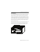
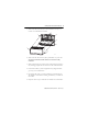
XM Dynamic Measurement Module 9 1. Make certain the keyswitch (D) on the terminal base unit (E) is at position 1 as required for the module. C D B E F A G 31886 2. Make certain the side connector (B) is pushed all the way to the left. You cannot install the module unless the connector is fully extended. 3. Make certain that the pins on the bottom of the module are straight so they will align properly with the connectors in the terminal base unit. 4.
XM Dynamic Measurement Module Set the Node Address The module has a DIP switch for setting the network node address. DIP switches 5 through 10 set the module’s node address using binary addressing. The module is shipped from the factory with the node address set to 63 (as shown below). DYNAMIC MEASUREMENT TIP TIP 1440-DYN02-01RJ DIP switches 1 through 4 are not used. The node addresses start with 1 for the module closest to the ACNR, and increase for each consecutive module.
XM Dynamic Measurement Module 11 Switch Settings for Node Address Switch Node Setting Addr SW5->SW10 Node Addr Switch Setting SW5->SW10 Node Addr Switch Setting SW5->SW10 Node Addr Switch Setting SW5->SW10 0(1) 000000 16 010000 32 100000 48 110000 1 000001 17 010001 33 100001 49 110001 2 000010 18 010010 34 100010 50 110010 3 000011 19 010011 35 100011 51 110011 4 000100 20 010100 36 100100 52 110100 5 000101 21 010101 37 100101 53 110101 6 000110 22
XM Dynamic Measurement Module Self-Test The XM module performs a self-test when it powers up. The self-test includes an LED test and a device test. During the LED test, the indicators will turn on independently and in sequence for approximately 0.25 seconds. The device test occurs after the LED test. The Module Status (MS) indicator is used to indicate the status of the device self-test. MS Indicator State Description Flashing Red and Green Device self-test is in progress.
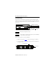
XM Dynamic Measurement Module 13 Status Indicators The module has seven LED indicators on top of the module. DYNAMIC MEASUREMENT 1440-DYN02-01RJ Status Indicators Indicator State Description Module Status (MS) Off No power applied to the module. Alternating Red/Green Module performing power-up self-test. Flashing Red • Application firmware is invalid or not loaded. Download firmware to the module. • Firmware download is currently in progress. Solid Red An unrecoverable fault has occurred.
XM Dynamic Measurement Module Indicator State Description Network Status (NS) Off Module is not online. • Module is autobauding. • No power applied to the module; look at Module Status LED. Channel 0 & Channel 1 Flashing Red One or more I/O connections are in the timed-out state. Solid Red Failed communications (duplicate MAC ID or bus-off). Flashing Green Module is online but no connections are currently established. Solid Green Module is online with connections currently established.
XM Dynamic Measurement Module 15 Indicator State Description Flashing Yellow Tachometer fault other than a transducer fault (for example no pulse received). Flashing Red Tachometer signal DC bias is not within the DC Low and High Limits. Setpoint Multiplier Off Alarm Limit Multiplier is not in effect. Solid Yellow Alarm Limit Multiplier is in effect. Relay Off Virtual relay is not activated. Solid Red Virtual relay is activated.
XM Dynamic Measurement Module Environmental Specifications Attribute Value Operating Temperature IEC 60068-2-1 (Test Ad, Operating Cold), IEC 60068-2-2 (Test Bd, Operating Dry Heat), IEC 60068-2-14 (Test Nb, Operating Thermal Shock): -20…70 °C (-4…158 °F) Non-Operating Temperature IEC 60068-2-1 (Test Ab, Unpackaged Non-operating Cold), IEC 60068-2-2 (Test Bb, Unpackaged Non-operating Dry Heat), IEC 60068-2-14 (Test Na, Unpackaged Non-operating Thermal Shock): -40…85 °C (-40…185 °F) Relative Humidi
XM Dynamic Measurement Module 17 Environmental Specifications Attribute Value Radiated RF Immunity IEC 61000-4-3: 10V/m with 1 kHz sine-wave 80% AM from 80…2000 MHz 10V/m with 200 Hz 50% Pulse 100% AM at 900 MHz 10V/m with 200 Hz 50% Pulse 100% AM at 1890 MHz 3V/m with 1 kHz sine-wave 80% AM from 2000…2700 MHz EFT/B Immunity IEC 61000-4-4: ±4 kV at 5 kHz on power ports ±2 kV at 5 kHz on signal ports ±2 kV at 5 kHz on communications ports Surge Transient Immunity IEC 61000-4-5: ±1 kV line-line (DM) an
XM Dynamic Measurement Module Certifications Certifications(1) (when product is marked) c-UL-us Description UL Listed Industrial Control Equipment, certified for US and Canada. See UL File E65584. UL Listed for Class I, Division 2 Group A,B,C,D Hazardous Locations, certified for U.S. and Canada. See UL File E194810. CE European Union 2004/108/EC EMC Directive, compliant with: • EN 61326-1; Meas./Control/Lab.
XM Dynamic Measurement Module 19 Additional Resources These documents contain additional information concerning related Rockwell Automation products. Resource Description XM Dynamic Measurement Module Terminal Base Installation Instructions, publication ICM-IN003 Provides details about how to install the terminal base for the XM Dynamic Measurement module.
Rockwell Automation Support Rockwell Automation provides technical information on the Web to assist you in using its products. At http://support.rockwellautomation.com, you can find technical manuals, a knowledge base of FAQs, technical and application notes, sample code and links to software service packs, and a MySupport feature that you can customize to make the best use of these tools.