Installation Instructions XM ControlNet Adapter Catalog Number 1440-ACNR Topic Page Important User Information 2 Environment and Enclosure 3 Prevent Electrostatic Discharge 4 North American Hazardous Location Approval 4 European Hazardous Location Approval 5 Before You Begin 6 XM Bus 7 Install the ControlNet Adapter 8 Product Dimensions 9 Wire the ControlNet Adapter 10 Set the Node Address 11 Install a Replacement ControlNet Adapter to an Existing System 12 Status Indicators 14
XM ControlNet Adapter Important User Information Solid state equipment has operational characteristics differing from those of electromechanical equipment. Safety Guidelines for the Application, Installation and Maintenance of Solid State Controls (Publication SGI-1.1 available from your local Rockwell Automation sales office or online at http://literature.rockwellautomation.com) describes some important differences between solid state equipment and hard-wired electromechanical devices.
XM ControlNet Adapter 3 Environment and Enclosure ATTENTION This equipment is intended for use in a Pollution Degree 2 industrial environment, in overvoltage Category II applications (as defined in IEC publication 60664-1), at altitudes up to 2000 meters (6562 ft) without derating. This equipment is considered Group 1, Class A industrial equipment according to IEC/CISPR Publication 11.
XM ControlNet Adapter Prevent Electrostatic Discharge ATTENTION This equipment is sensitive to electrostatic discharge, which can cause internal damage and affect normal operation. Follow these guidelines when you handle this equipment: • Touch a grounded object to discharge potential static. • Wear an approved grounding wriststrap. • Do not touch connectors or pins on component boards. • Do not touch circuit components inside the equipment. • Use a static-safe workstation, if available.
XM ControlNet Adapter 5 European Hazardous Location Approval European Zone 2 Certification (The following applies when the product bears the Ex or EEx Marking) This equipment is intended for use in potentially explosive atmospheres as defined by European Union Directive 94/9/EC and has been found to comply with the Essential Health and Safety Requirements relating to the design and construction of Category 3 equipment intended for use in potentially explosive atmospheres, given in Annex II to this Directiv
XM ControlNet Adapter Before You Begin The XM ControlNet adapter is a communication adapter for XM modules. The adapter provides an interface for controlling XM modules on an XM Bus and transferring data to the processor over a ControlNet network.
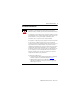
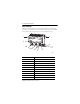
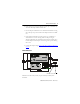
XM ControlNet Adapter 7 XM Bus The XM Bus connector, located on the side of the adapter, connects the adapter to the XM modules on the DIN rail, as illustrated below. XM® 1 1 1 Class 2 Supply 24 V 24 V COM The XM Bus connector passes power and XM network communications between the connected modules. The XM network communicates using standard DeviceNet protocols and CAN transceivers, but it does not share the same specifications for the media (wire) and isolation characteristics.
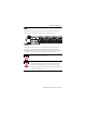
XM ControlNet Adapter Install the ControlNet Adapter If you insert or remove the module while backplane power is on, an electrical arc can occur. This could cause an explosion in hazardous location installations. ATTENTION Be sure that power is removed or the area is nonhazardous before proceeding. This product is grounded through the DIN rail to chassis ground. Use zinc plated yellow-chromate steel DIN rail to assure proper grounding.
XM ControlNet Adapter 9 2. Hook the lip on the rear of the adapter onto the top of the DIN rail, and rotate the adapter module onto the rail. 3. Press the adapter module down onto the DIN rail until flush. Locking tab C will snap into position and lock the adapter module to the DIN rail. 4.
XM ControlNet Adapter Wire the ControlNet Adapter If you connect or disconnect wiring while the field-side power is on, an electrical arc can occur. This could cause an explosion in hazardous location installations. Be sure that power is removed or the area is nonhazardous before proceeding. WARNING If you connect or disconnect the communications cable with power applied to this module or any device on the network, an electrical arc can occur.
XM ControlNet Adapter 11 2. Connect the redundant ControlNet network cable to connector B. ATTENTION When connecting wiring, torque terminal screws C, D, E, and F to 0.8 Nm (7 lb-in). 3. Connect +V DC power to the lower connector, terminal F or D. 4. Connect -V common to the upper connector, terminal E or C. Set the Node Address Set the network address using the 2-button pushwheel switch (G). Valid settings range from 01 to 99. 2 5 Press either the + or - buttons to change the number.
XM ControlNet Adapter Install a Replacement ControlNet Adapter to an Existing System ATTENTION If you insert or remove the module while backplane power is on, an electrical arc can occur. This could cause an explosion in hazardous location installations. Be sure that power is removed or the area is nonhazardous before proceeding. ATTENTION WARNING WARNING Do not remove or replace an Adapter Module while power is applied.
XM ControlNet Adapter 13 Install the replacement adapter on the DIN rail as follows. 1. Before installing the replacement adapter, make certain the XM Bus connector of the terminal base is fully retracted into the base unit. 2. Position the replacement adapter on the DIN rail. The hook on the terminal base slides under the edge of the adapter. 3. Push down and in at the same time to lock the adapter to the DIN rail.
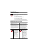
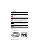
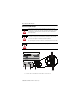
XM ControlNet Adapter Status Indicators 1440-ACNR ControlNet XM Adapter Channel A Channel B Module Status Back Plane Status 2 A 5 B Indicator State Description Module Status Off No power applied to the device Alternating Red/Green LED power up test (module self-test) Flashing Red Recoverable fault has occurred: • Firmware (NVS) update • MAC ID changed • CPU load exceeded Solid Red Unrecoverable fault has occurred: •Self test failure (checksum failure at power up, RAM test failure a
XM ControlNet Adapter 15 Indicator State Description CH A and CH B Both Off Viewed Together Reset, no power or entire network interface deactivated Alternating Red/Green Self test mode Alternating Red/Off Bad/invalid node configuration (such as duplicate MAC ID) Both Red Failed link interface or failed module CH A and CH B Off Channel disabled or channel not supported Viewed Individually Flashing Red/Green Invalid link configuration Flashing Red/Off Severe Link error - link fault or no M
XM ControlNet Adapter Specifications XM ControlNet Adapter - 1440-ACNR Attribute Value Enclosure Type Rating None (open-style) Input Voltage 24V DC Current Draw Max 120 mA XM Bus Output 24V DC, 3 A Max Isolation Voltage 50V (continuous), Basic Insulation Type Type tested at 900V AC for 60 s, between ControlNet to system and ControlNet to power. Wire Size Power connections: 0.34... 2.1 mm2 (22...14 AWG) solid or stranded copper wire rated at 75 °C (167 °F ) or greater 1.2 mm (3/64 in.
XM ControlNet Adapter 17 Environmental Specifications Attribute Value Non-Operating Temperature IEC 60068-2-1 (Test Ab, Unpackaged Non-operating Cold), IEC 60068-2-2 (Test Bb, Unpackaged Non-operating Dry Heat), IEC 60068-2-14 (Test Na, Unpackaged Non-operating Thermal Shock): -40…85 °C (-40…185 °F) Relative Humidity IEC 60068-2-30 (Test Db, Unpackaged Damp Heat): 5…95% non-condensing Vibration IEC 60068-2-6 (Test Fc, Operating): 5 g @ 10…500 Hz Operating Shock IEC 60068-2-27 (Test Ea, Unpackaged Sh
XM ControlNet Adapter Environmental Specifications Attribute Value Surge Transient Immunity IEC 61000-4-5: ±1 kV line-line (DM) and ±2 kV line-earth(CM) on power ports ±2 kV line-earth(CM) on communications ports Conducted RF Immunity IEC 61000-4-6: 10V rms with 1 kHz sine-wave 80% AM from 150 kHz…80 MHz Certifications (when product is marked) Certifications(1) Description c-UL-us UL Listed Industrial Control Equipment, certified for US and Canada. See UL File E65584.
XM ControlNet Adapter 19 Additional Resources These documents contain additional information concerning related Rockwell Automation products. Resource Description Dynamic Measurement Module Installation Instructions, publication ICM-IN002 Provides information about mounting the Dynamic Measurement module and technical specifications.
Rockwell Automation Support Rockwell Automation provides technical information on the Web to assist you in using its products. At http://support.rockwellautomation.com, you can find technical manuals, a knowledge base of FAQs, technical and application notes, sample code and links to software service packs, and a MySupport feature that you can customize to make the best use of these tools.