
Manual

Rockwell Automation Publication 1426-UM001F-EN-P - November 2013 39
Install the PowerMonitor 5000 Unit Chapter 2
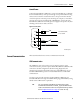
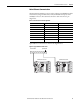
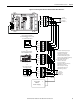
Figure 20 - Connecting a Powermonitor 5000 Unit to Other DeviceNet Devices
121 Ω
Terminating
Resistor
(See Note 2)
121 Ω
Terminating
Resistor
(see Note 2)
Personal Computer With
1784-PCDPCMCIA Interface Card
Or
1770-KFD Interface Box
Or
SLC™ Controller With
1747-SDN Scanner
1) Example network protrayed.
For detailed DeviceNet
installations, including
cable requirements, refer to
the DeviceNet Cable System
Planning and Installation Manual,
publication DNET-UM072.
2) Terminating resistors
must be connected
to each end of the
DeviceNet network. Omit the
terminating resistors
if the devices are already
equipped with internal
terminating resistors.
V-
V+
CAN_L
SHLD
CAN_H
V-
V+
CAN_L
SHLD
CAN_H
V-
V+
CAN_L
SHLD
CAN_H
V-
V+
CAN_L
SHLD
CAN_H
+
-
DeviceNet
24V DC
Power Supply
Or Other DeviceNet
Scanner Devices
Or
ControlLogix® Controller
With 1756-DNB Scanner
Virtual Wiring
Correction
---- S1
S2
---- S3
S4
---- S com
S com
---- K
Y
---- Z
R1 O
---- R1 com
R1 C
---- R2 O
R2 com
---- R2 C
R3 O
---- R3 com
R3 C
Module
status
Network
status
Cong Lock
EtherNet √
IP
PowerMonitor 5000
Power
USB
Device
USB
Host
LNK
ACT
I 1
I 2
I 3
I 4
L1
L2
GND
24V
com
Scom
S n
Internal
24VDC
K
Y
Z
Rx O
Rx com Rx C
V1
V2
V3
VN
VG
1
DS NS
2345
DeviceNet
12345