
Manual

38 Rockwell Automation Publication 1426-UM001F-EN-P - November 2013
Chapter 2 Install the PowerMonitor 5000 Unit
Optional DeviceNet Network Communication
An optional DeviceNet port can be factory-installed in PowerMonitor 5000
units with a catalog number ending in -DNT, and can also be purchased from
Rockwell Automation and installed by the user.
For information on installing the optional communication card, see the
PowerMonitor 5000 Optional Communication Modules Installation
Instructions, publication 1426-IN002
.
For detailed DeviceNet system installation information, including cable lengths,
the placement of terminating resistors, power supplies, and other media
components, refer to the DeviceNet Cable System Planning and Installation
Manual, publication DNET-UM072
.
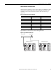
Install suitable terminating resistors at the ends of the DeviceNet cable.
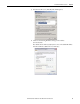
Configuration options for optional DeviceNet communication include the node
address (MAC ID) and data rate. Defaults are node 63 and 125 Kbps.
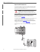
ATTENTION: Power must be removed from the power monitor before inserting
or removing an optional communication card. Inserting or removing an
optional communication card under power can damage the card or the power
monitor.
IMPORTANT
You must install and wire a suitable 24V DC power supply to the V+ and V-
conductors in the DeviceNet cable. The power monitor consumes less than
50 mA from the DeviceNet 24V DC supply.
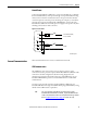
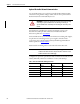
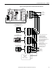
Table 7 - DeviceNet Terminal Block Wiring Connections
Terminal Signal Function Color
1 COM (V-) Common Black
2 CAN_L Signal Low Blue
3 SHIELD Shield Uninsulated
4 CAN_H Signal High White
5 VDC+ (V+) Power Supply Red