
Manual

Rockwell Automation Publication 1426-UM001F-EN-P - November 2013 379
Appendix D
PowerMonitor 5000 Waveform Capture and
Compression (M6 model)
Waveform recordings in the PowerMonitor 5000 M6 model consist of a series of
cycle-by-cycle magnitude and angle data for each spectral component (harmonic)
from DC through the 127th harmonic. To reduce the size of waveform records
without losing significant resolution, the data is compressed before writing to the
waveform file. To display the record as a waveform, the file data must be
decompressed, and then an inverse FFT performed to obtain a series of time-
domain voltage and current data that can then be plotted in a graphic format.
Compression Algorithm
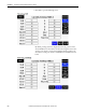
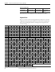
Three types of floating point number representations are used, with 32, 16 and
12 bits. The formats are summarized in the table.
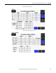
The table below defines how compression is applied to magnitude and angle
values of specific harmonic orders.
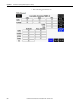
The various number encodings are packed into the file in the following way:
Type Total bits Bits
precision
Sign bits Exponent
bits
Significand
bits
Exponent
bias
IEEE 754
Single
32 24 1 8 23 127
16 bit
encoded
16 12 1 4 11 TBD
12 bit
encoded
128147TBD
Data / encoding 32-bit 16-bit 12-bit
Magnitude DC thru 15th - 16th thru 127th
Angle - DC thru 15th 16th thru 127th
Table 196 - 32-bit (IEEE 754)
Byte offset 0 Byte offset 1 Byte offset 2 Byte offset 3
Low byte Next lowest byte Next highest byte High byte
Table 197 - 16-bit Encoding
Byte offset 0 Byte offset 1
Low byte High byte