
Manual

Rockwell Automation Publication 1426-UM001F-EN-P - November 2013 37
Install the PowerMonitor 5000 Unit Chapter 2
Native Ethernet Communication
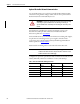
The PowerMonitor 5000 unit connects easily to industry-standard Ethernet hubs
and switches by using standard CAT-5 UTP (unshielded twisted-pair) cables
with RJ45 connectors. The table below shows the cable and connector pin
assignments.
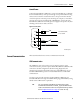
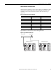
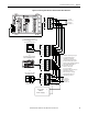
Typical Ethernet connections are shown in the diagram below.
Figure 19 - Typical Ethernet Connections
Table 6 - Cable and Connector Pin Assignments
Terminal Signal Function
1TX+TX+
2TX-TX-
3RX+RX+
4
5
6RX-RX-
7
8
Virtual Wiring
Correction
---- S1
S2
---- S3
S4
---- S com
S com
---- K
Y
---- Z
R1 O
---- R1 com
R1 C
---- R2 O
R2 com
---- R2 C
R3 O
---- R3 com
R3 C
Module
status
Network
status
Cong Lock
EtherNet √
IP
PowerMonitor 5000
Power
USB
Device
USB
Host
LNK
ACT
I 1
I 2
I 3
I 4
L1
L2
GND
24V
com
Scom
S n
Internal
24 VDC
K
Y
Z
Rx O
Rx com Rx C
V1
V2
V3
VN
VG
C
C
O M M U N I C A T I O N P O
R T
Virtual Wiring
Correction
---- S1
S2
---- S3
S4
---- S com
S com
---- K
Y
---- Z
R1 O
---- R1 com
R1 C
---- R2 O
R2 com
---- R2 C
R3 O
---- R3 com
R3 C
Module
status
Network
status
Cong Lock
EtherNet √
IP
PowerMonitor 5000
Power
USB
Device
USB
Host
LNK
ACT
I 1
I 2
I 3
I 4
L1
L2
GND
24V
com
Scom
S n
Internal
24 VDC
K
Y
Z
Rx O
Rx com Rx C
V1
V2
V3
VN
VG
C O M M U N I C A T I O N P O R T
Ethernet Switch Uplink to LAN
PowerMonitor 5000 Unit PowerMonitor 5000 Unit