
Manual

Rockwell Automation Publication 1426-UM001F-EN-P - November 2013 311
PowerMonitor 5000 Unit Data Tables Appendix A
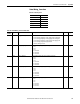
Status.Wiring_Corrections
Table 119 - Table Properties
CIP Instance Number 834
PCCC File Number N43
No. of Elements 14
Length in Words 14
Data Type Int16
Data Access Read Only
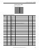
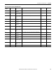
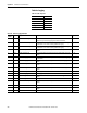
Table 120 - Status.Wiring_Corrections Data Table
Element
Number
Type Tag Name Description Default Range
0 Int16 Wiring_Correction_Commands 0 = No command
1 = Correct wiring by using Range 1 results, Lagging 97 PF to Leading 89 PF
2 = Correct wiring by using Range 2 results, Lagging 85 PF to leading 98 PF
3 = Correct wiring by using Range 3 results, Lagging 52 PF to lagging 95 PF
4 = Correct wiring by using manual input parameters
5 = Remove all wiring corrections
00…5
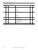
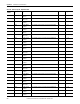
1 Int16 Input_V1_Mapping This parameter logically maps a physical voltage channel to V1.
1 = V1
2 = V2
3 = V3
-1 = V1 inverted
-2 = V2 inverted
-3 = V3 inverted
1-3…-1
1…3
2 Int16 Input_V2_Mapping This parameter logically maps a physical voltage channel to V2.
1 = V1
2 = V2
3 = V3
-1 = V1 inverted
-2 = V2 inverted
-3 = V3 inverted
2-3… -1
1…3
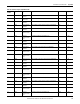
3 Int16 Input_V3_Mapping This parameter logically maps a physical voltage channel to V3.
1 = V1
2 = V2
3 = V3
-1 = V1 inverted
-2 = V2 inverted
-3 = V3 inverted
3-3…-1
1 …3
4 Int16 Input_I1_Mapping This parameter logically maps a physical current channel to I1.
1 = I1
2 = I2
3 = I3
-1 = I1 inverted
-2 = I2 inverted
-3 = I3 inverted
1-3…-1
1…3