
Manual

270 Rockwell Automation Publication 1426-UM001F-EN-P - November 2013
Appendix A PowerMonitor 5000 Unit Data Tables
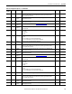
23 Int16 L1_G5 Input 3 Selects the third input parameter for the gate. Each gate has four inputs.
0 = Disabled
1 = Setpoint 1
2 = Setpoint 2
3 = Setpoint 3
…
20 = Setpoint 20
IMPORTANT: Negative numbers invert the input.
0 -20…20
24 Int16 L1_G5 Input 4 Selects the fourth input parameter for the gate. Each gate has four inputs.
0 = Disabled
1 = Setpoint 1
2 = Setpoint 2
3 = Setpoint 3
…
20 = Setpoint 20
IMPORTANT: Negative numbers invert the input.
0 -20…20
25 Int16 Logic Level 1
Gate 6 Function
Selects the logic type
0 = disabled
1 = AND
2 = NAND
3 = OR
4 = NOR
5 = XOR
6 = XNOR
IMPORTANT: XOR and XNOR use Inputs 1 and 2 only.
00…6
26 Int16 L1_G6 Input 1 Selects the first input parameter for the gate. Each gate has four inputs.
0 = Disabled
1 = Setpoint 1
2 = Setpoint 2
3 = Setpoint 3
…
20 = Setpoint 20
IMPORTANT: Negative numbers invert the input.
0 -20…20
27 Int16 L1_G6 Input 2 Selects the second input parameter for the gate. Each gate has four inputs.
0 = Disabled
1 = Setpoint 1
2 = Setpoint 2
3 = Setpoint 3
…
20 = Setpoint 20 IMPORTANT: Negative numbers invert the input.
0 -20…20
28 Int16 L1_G6 Input 3 Selects the third input parameter for the gate. Each gate has four inputs.
0 = Disabled,
1 = Setpoint 1,
2 = Setpoint 2,
3 = Setpoint 3
…
20 = Setpoint 20
IMPORTANT: Negative numbers invert the input.
0 -20…20
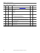
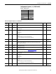
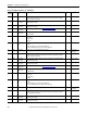
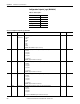
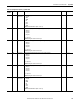
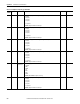
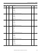
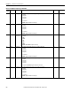
Table 70 - Configuration.Setpoint_Logic Data Table
Element
Number
Type Tag Name Description Default Range