
Manual

250 Rockwell Automation Publication 1426-UM001F-EN-P - November 2013
Appendix A PowerMonitor 5000 Unit Data Tables
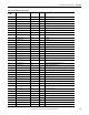
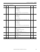
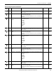
18 Real Status_Input_1_Input_Scale When a status pulse is received the count is increased by the scale factor.
(Input pulse * input scale) added to total status count.
11…
1,000,000
19 Real Status_Input_2_Input_Scale When a status pulse is received the count is increased by the scale factor.
(Input pulse * input scale) added to total status count.
11…
1,000,000
20 Real Status_Input_3_Input_Scale When a status pulse is received the count is increased by the scale factor.
(Input pulse * input scale) added to total status count.
11…
1,000,000
21 Real Status_Input_4_Input_Scale When a status pulse is received the count is increased by the scale factor.
(Input pulse * input scale) added to total status count.
11…
1,000,000
22 Real Unit_Error_Action This parameter determines the action when a unit error occurs.
0 = Safe Mode on error and make status LED solid red
1 = Perform a firmware reset.
10…1
23 Real Software_Error_Log_Full_Action This parameter determines the action when a firmware failure is detected and the
error log is full.
0 = Safe Mode on error, make status LED solid red and wait for error collection and
clear log command.
1 = Perform a firmware reset.
10…1
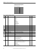
24 Real Default_KYZ_State_On_Comm_
Loss
The Default output state on communication loss defines the behavior of the output if
the power monitor experiences a loss of communication.
0 = Last state/resume
1 = Last state/freeze
2 = De-energize/resume
3 = De-energize/freeze
4 = Local control
00…4
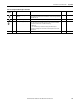
25 Real Default_Relay_1_State_On_
Comm_Loss
The Default output state on communication loss defines the behavior of the output if
the power monitor experiences a loss of communication.
0 = Last state/resume
1 = Last state/freeze
2 = De-energize/resume
3 = De-energize/freeze
4 = Local control
00…4
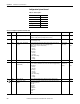
26 Real Default_Relay_2_State_On_
Comm_Loss
The Default output state on communication loss defines the behavior of the output if
the power monitor experiences a loss of communication.
0 = Last state/resume
1 = Last state/freeze
2 = De-energize/resume
3 = De-energize/freeze
4 = Local control
00…4
27 Real Default_Relay_3_State_On_
Comm_Loss
The Default output state on communication loss defines the behavior of the output if
the power monitor experiences a loss of communication.
0 = Last state/resume
1 = Last state/freeze
2 = De-energize/resume
3 = De-energize/freeze
4 = Local control
00…4
28…49 Real Reserved Future Use 0 0
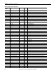
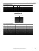
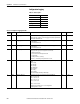
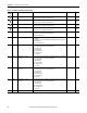
Table 56 - Configuration.System.General Data Table
Element
Number
Type Tag Name Description Default Range