
Manual


246 Rockwell Automation Publication 1426-UM001F-EN-P - November 2013
Appendix A PowerMonitor 5000 Unit Data Tables
Configuration.Metering.Basic
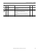
Table 53 - Table Properties
CIP Instance Number 802
PCCC File Number F11
No. of Elements 33
Length in Words 66
Data Type Real
Data Access Read/Write
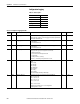
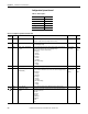
Table 54 - Configuration.Metering.Basic Data Table
Element
Number
Type Tag Name Description Default Range
0 Real Metering_Mode Configures the input wiring for metering.
0 = Demo
1 = Split-phase
2 = Wye
3 = Delta 2 CT
4 = Delta 3 CT
5 = Open Delta 2 CT
6 = Open Delta 3 CT
7 = Delta Gnd B Ph 2 CT
8 = Delta Gnd B Ph 3 CT
9 = Delta High Leg
20…9
1 Real V1_V2_V3_PT_Primary The primary voltage value of the PT transformer. 480 0…1,000,000
2 Real V1_V2_V3_PT_Secondary The secondary voltage value of the PT transformer. 480 0…690
3 Real I1_I2_I3_CT_Primary The primary ampere value of the CT transformer. 5 0…1,000,000
4 Real I1_I2_I3_CT_Secondary The secondary ampere value of the CT transformer. 5 5
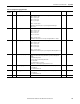
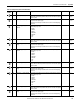
5 Real VN_PT_Primary The primary voltage value of the PT transformer. 480 0…1,000,000
6 Real VN_PT_Secondary The secondary voltage value of the PT transformer. 480 0…690
7 Real I4_CT_Primary The primary ampere value of the CT transformer. 5 0…1,000,000
8 Real I4_CT_Secondary The secondary ampere value of the CT transformer. 5 5
9 Real Nominal_System_LL_Voltage Nominal line to line voltage value or line to line voltage rating of the system being
metered.
480 0…1,000,000
10 Real Nominal_System_Frequency Nominal frequency of the system. 60 50 …60
11 Real Realtime_Update_Rate Selects the update rate for the realtime table and the setpoint calculations.
0 = Single cycle averaged over 8 cycles
1 = Single cycle averaged over 4 cycles
2 = 1 cycle with no averaging
3 = 200ms per EN61000-4-30 (M6 model only)
00…2
12 Real Demand_Source When item ‘Demand Broadcast Master Select’ of the Ethernet table is set to master a
selection of 0…2 and 4 sets the type of master input. In this case item 3 is ignored.
When the ‘Demand Broadcast Master Select’ of the Ethernet table is set to slave then
any of these inputs can set the end of the demand period.
0=Internal Timer
1=Status Input 2
2=Controller Command
3=Ethernet Demand Broadcast
00…3