
Manual


Rockwell Automation Publication 1426-UM001F-EN-P - November 2013 19
Install the PowerMonitor 5000 Unit Chapter 2
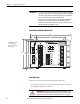
3. Use M4 or #8 screws to mount the power monitor to your panel with
1.16 N•m (10 lb•in) of torque.
4. Ground the power monitor on a ground bus with a low-impedance earth
ground connection.
5. Connect the ground bus to a functional earth ground on the panel.
Wire the PowerMonitor 5000
Unit
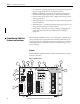
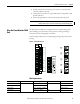
The PowerMonitor 5000 unit is equipped with screw terminals with pressure
plates and finger protection for the control power, I/O wiring, and voltage
connections. The I/O wiring block is removable.
Current sensing conductors are routed through openings in the power monitor
housing.
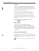
Figure 2 - Terminal Block Layout
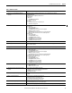
Wire Requirements
IMPORTANT
The upper mounting slots are equipped with protective conductor terminals,
that must make metal-to-metal contact with the grounded mounting panel.
L1
L2
GND
24V
com
V1
V2
V3
VN
VG
---- S1
S2
---- S3
S4
---- S com
S com
---- K
Y
---- Z
R1 O
---- R1 com
R1 C
---- R2 O
R2 com
---- R2 C
R3 O
---- R3 com
R3 C
Wiring Category Wire Type Wire Size Range Wires per Terminal Recommended Torque
Control Power Cu - 75 °C (167 °F) 0.25…2.5 mm
2
(22…14 AWG) 2 max 1.27 N•m (11.24 lb•in)
Input/Output (I/O) 0.5…0.8 mm
2
(20…18 AWG) 0.68 N•m (6 lb•in)
Voltage Sensing 0.75…2.5 mm
2
(18…14 AWG) 1.50 N•m (13.3 lb•in)
Current Sensing 4 mm
2
max (12 AWG max) 1 max N/A