
Manual


Rockwell Automation Publication 1426-UM001F-EN-P - November 2013 13
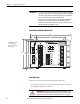
PowerMonitor 5000 Unit Overview Chapter 1
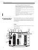
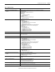
Table 1 - Hardware Features
Feature Description
1. Ethernet port – standard RJ45 jack with status
indicators
Ethernet port hardware is included on all models. These protocols and functions are supported:
• EtherNet/IP network
• HTML web page for configuration and data access
Ethernet indicators
• LNK indicator
– Solid GREEN: IP link established
– Off: No link established
• ACT indicator
– Flashing YELLOW: Data present on Ethernet port
– Off: No data activity present
2. Optional communication port DeviceNet and ControlNet networks
• Module Status
– OFF: No control power
– Flashing GREEN/RED: Self-test
– Flashing GREEN: Power monitor has not been configured
– GREEN: Power monitor is running
– Flashing RED: Power monitor has detected a recoverable minor fault
– RED: Power monitor has detected a non-recoverable major fault
• Network Status
– OFF: No control power
– Flashing GREEN/RED: Self-test
– Flashing GREEN: No CIP connection
– Solid GREEN: CIP connection established
– Flashing RED: CIP connection timed out
– Solid RED: Duplicate address detected
3. USB host port USB standard A receptacle. Not used in this model.
4. USB device port The USB device port is a USB Mini-B receptacle that accepts standard USB Mini-B plugs, for connection to a host device,
such as a notebook computer.
5. Configuration Lock switch When enabled, this switch prevents changes in configuration that can affect revenue accuracy.
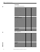
6. Device and Network status indicators • Device status
– OFF: No control power
– Flashing GREEN/RED: Self-test
– Flashing GREEN: Power monitor has not been configured
– GREEN: Power monitor is running
– Flashing RED: Power monitor has detected a recoverable minor fault
– RED: Power monitor has detected a non-recoverable major fault
• Network status (Native Ethernet port)
– OFF: No control power
– Flashing GREEN/RED: Self-test
– Flashing GREEN: No CIP connection
– Solid GREEN: CIP connection established
– Flashing RED: CIP connection timed out
– Solid RED: Duplicate IP address detected
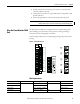
7. Power • Power status
– OFF: No control power
– GREEN: Control power is present
8. Status input, KYZ output, and control relay wiring
terminals
• Four internally-powered (24V DC) status inputs
• Status input 2 can be used for demand period synchronization
• KYZ DPDT solid-state relay for signaling use
• Three DPDT control relays
9. Control power and ground wiring terminals • 120…240V AC, 50/60 Hz or 120...240V DC
• 24V DC
10.Voltage sensing wiring terminals • Direct connect to up to 690V AC 3-phase line to line
• Maximum nominal line to ground voltage 690
• Use potential transformers (PTs) for higher voltages
• Neutral voltage and ground voltage connections
11.Current sensing wiring openings • Nominal input current 5 A
• Use current transformers (CTs) to connect to power system
12.Virtual wiring correction indicator Indicates that the sensing voltage and/or current wiring has been modified in the power monitor configuration.