
Manual

Rockwell Automation Publication 1425-UM001A-EN-P - January 2012 43
Software Interface Chapter 3
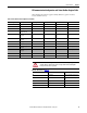
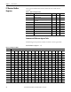
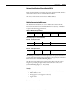
RF Communication Configuration and Status Modbus Register Table
This table lists the common registers used by all devices (power monitors,
routers, and PC receiver).
Table 22 - RF Communication Configuration and Status
Modbus Register Description Type/Length Storage Unit Access
201 Hop count U16 V R
202 First hop ID U16 V R
203 Last hop ID U16 V R
204 RSSI (high byte) and Supply
voltage (low byte)
U16 V R
220 Device ID (high byte and
low byte)
U16 NV R
221 Group ID (high byte and
low byte)
U16 NV R
222 Sampling interval U16 NV R
224 Network channel (11…26) U16 NV R
347 Device ID (high byte and
low byte)
U16 NV See warning below
348 Group ID (high byte and
low byte)
U16 NV See warning below
349 Sampling interval U16 V W
351 Network channel (11…26) U16 NV W
WARNING: Do not change the value of the Device ID or Group ID, registers 347
and 348. Doing so will cause the device to drop off the network and require
factory service to restore operation.
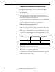
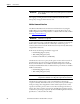
Table 23 - Information for Table 22
Term Description Comments
NV Nonvolatile Value is restored after a power cycle
V Volatile Value is not restored after a power
cycle
U16 Unsigned 16-bit INT Range 0…65,535
High byte Bits 8…15
Low byte Bits 0…7