
Manual


32 Rockwell Automation Publication 1425-UM001A-EN-P - January 2012
Chapter 2 Hardware Installation
Network Commissioning
This section describes the module identification and PC Receiver connection.
Module Identification
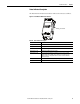
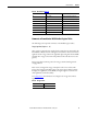
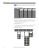
Figure 24 - Label
Each module has two identification numbers: Group ID and Device ID, each
defined by 2 bytes.
The Group ID and Device ID are printed on labels on the following:
• PowerMonitor W250 unit front side
• Router or PC Receiver rear side
The devices are addressed at the factory, as shown in the following table.
Table 11 - Label Information
Item Description
1Group ID
2 Device ID
3 Firmware revision
4 Manufacture date code
TIP
All modules, including the PC Receiver, must be set with the same Group ID to
communicate together on the same network. All parts are delivered from
factory with default GID: 111.111.
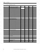
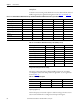
Table 12 - Device Addresses
Device Type Device High byte Low Byte
(Modbus address)
End Node Devices (high
byte 1…159)
PowerMonitor W250 1…30 1…216
Reserved 41…159 100 …216
Router Devices (high byte
160 …255, except 248 &
249)
Reserved 160…209 1…216
Router 210…219, 240…247 217 …246
PC Receiver PC Receiver 160 …255 (except 248 &
249)
247