
Manual


16 Rockwell Automation Publication 1425-UM001A-EN-P - January 2012
Chapter 2 Hardware Installation
Network Deployment
Recommendations
Prior to defining your network and the elements location, read the following
information.
Planning Your Installation
Follow this information before installing your PowerMonitor W250 unit.
Building Audit
Mesh devices all communicate via wireless radio frequencies and are influenced
by several factors (electrical wires, metal objects, heavy concrete walls, direction
of installed devices, and so on).
Consider the following items in network configuration:
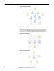
• Number of floors, layout
• Network topology - dense versus spread out/serial
• Type of bu ilding material
• Power availability for routers and receivers not attached to meters
• Any known obstacles or RF interferences (for example, heating pipes,
electrical room)
• ‘Bridge’ router placement
• Detect other 2.4 GHz interference
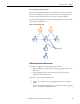
Walls and Floors
Inside a building, radio waves deflect on walls and other objects create
interference.
When the PowerMonitor W250 unit or other system components are mounted
on a wall or where the RF signal travels through a wall or other construction, be
aware of the materials used in the construction (both sides). Note that certain
materials will reduce the signal strength and maximum distance between nodes.
Usually, floors are most difficult for radio frequency signals to penetrate due to
materials used (for example, concrete, cement, and tiles). So, consider placing
routers in stairways and other open spaces available between floors.
IMPORTANT
We recommend you apply power to the Wireless PC Receiver before applying
power to the PowerMonitor W250 unit or Router nodes.
ATTENTION: All devices are designed for indoor use only.