
Manual


12 Rockwell Automation Publication 1425-UM001A-EN-P - January 2012
Chapter 1 PowerMonitor W250 Unit Overview
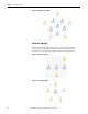
Wireless Router Description
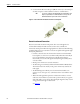
The Wireless Router extends the range of the mesh network to accommodate
longer distances between nodes, overcome physical barriers, and provide for
multiple signal routing.
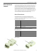
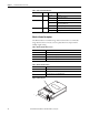
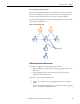
Figure 7 - Wireless Router
Table 5 - PC Receiver Status Indicators
Indicator Position Status Description
Power Left Green ON Power OK
OFF Power has been removed
Communication Middle Green ON Modbus mode
Amber ON Standard (MASC) mode for Meshscape Network Monitor or
Meshscape programmer use
Red ON Programming in progress
RF activity Right Green ON Initialization, PC Receiver not operating
Flashing Green RF activity
Table 6 - Wireless Router and Accessories
Cat. No. Description
1425-NOD Wireless Power Monitor Router
1425-ADR1 PowerMonitor Router Adapter, US
1425-ADR2 PowerMonitor Router Adapter, EMEA
1425-ADR3 PowerMonitor Router Adapter, UK
Table 7 - Wireless Router Features
Item Description
1 Status indicators (see Table 8)
2 Power supply connector 6…30V DC
3 Connector panel access cover (ON/OFF switch)
2
3
1