User Manual PowerMonitor Wireless 250 Monitor Catalog Numbers 1425
Important User Information Solid-state equipment has operational characteristics differing from those of electromechanical equipment. Safety Guidelines for the Application, Installation and Maintenance of Solid State Controls (publication SGI-1.1 available from your local Rockwell Automation® sales office or online at http://www.rockwellautomation.com/literature/) describes some important differences between solid-state equipment and hard-wired electromechanical devices.
Table of Contents Preface Additional Resources . . . . . . . . . . . . . . . . . . . . . . . . . . . . . . . . . . . . . . . . . . . . . . . 5 Chapter 1 PowerMonitor W250 Unit Overview About the PowerMonitor W250 Unit . . . . . . . . . . . . . . . . . . . . . . . . . . . . . . . 7 PowerMonitor W250 Unit . . . . . . . . . . . . . . . . . . . . . . . . . . . . . . . . . . . . . . . . . 9 Wireless Mesh Network Components . . . . . . . . . . . . . . . . . . . . . . . . . . . . .
Table of Contents Notes: 4 Rockwell Automation Publication 1425-UM001A-EN-P - January 2012
Preface The information in this manual applies to the PowerMonitor W250 wireless power monitor. Additional Resources These documents contain additional information concerning related products from Rockwell Automation. Resource Description Industrial Automation Wiring and Grounding Guidelines, publication 1770-4.1 Provides general guidelines for installing a Rockwell Automation industrial system. Product Certifications website, http://www.ab.
Preface Notes: 6 Rockwell Automation Publication 1425-UM001A-EN-P - January 2012
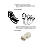
Chapter 1 PowerMonitor W250 Unit Overview About the PowerMonitor W250 Unit The PowerMonitor W250 product family provides a cost-effective, wireless submetering solution for use with RSPower™, version 5.0 or later, data visualization and RSEnergyMetrix™, version 1.9 or later, energy monitoring, load profiling, and reporting software.
Chapter 1 PowerMonitor W250 Unit Overview The PowerMonitor W250 unit consists of three main parts: • Wireless power monitor: The PowerMonitor W250 unit is a sub-meter that measures and calculates several electrical parameters. The unit is equipped with pre-wired split core current transformers or Rogowski coils and embedded wireless data transmission capabilities.
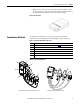
PowerMonitor W250 Unit Overview Chapter 1 • Wireless router: The router is a repeater that extends the distance of the wireless transmission range and can provide multiple signal paths between the PowerMonitor W250 unit and the receiver when needed. Figure 4 - Wireless Router The PowerMonitor W250 unit is a 3-phase electric meter with wireless communication. The following illustration highlights its major components.
Chapter 1 PowerMonitor W250 Unit Overview PowerMonitor W250 Data Overview The PowerMonitor W250 unit sends data to the wireless receiver periodically. The meter data is split into three sections: • Cumulative Energy Consumption Metering Data: The power monitor transmits accumulated real, reactive, and apparent energy, per-phase and total, once per minute. The transmission is accompanied with the time stamp of the most recent reading.
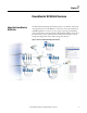
PowerMonitor W250 Unit Overview Wireless Mesh Network Components Chapter 1 The PowerMonitor W250 unit communicates by using a wireless mesh network, capable of forming multiple paths in order to increase the robustness of the network and respond to dynamic radio environments that may obstruct radio transmission. In general, mesh network nodes are positioned at the point of sensing and control to eliminate or minimize wiring.
Chapter 1 PowerMonitor W250 Unit Overview Table 5 - PC Receiver Status Indicators Indicator Position Status Description Power Left Green ON Power OK OFF Power has been removed Green ON Modbus mode Amber ON Standard (MASC) mode for Meshscape Network Monitor or Meshscape programmer use Red ON Programming in progress Green ON Initialization, PC Receiver not operating Flashing Green RF activity Communication RF activity Middle Right Wireless Router Description The Wireless Router exten
PowerMonitor W250 Unit Overview Chapter 1 Table 8 - Wireless Router Status Indicators Indicator Status Description PWR ON Power ON. OFF No power. Flashing Router detects RF activity. The RF activity indicator will flash when detecting valid packets (packets destined for device) and may also flash when detecting invalid packets (packets destined for other devices) or environmental noise. Only valid packets are processed by the device. OFF No RF activity detected.
Chapter 1 PowerMonitor W250 Unit Overview Notes: 14 Rockwell Automation Publication 1425-UM001A-EN-P - January 2012
Chapter 2 Hardware Installation This chapter describes how to install the hardware to set up the Wireless Mesh Sub-meter Network. Safety Considerations ATTENTION: Only qualified personnel, following accepted safety procedures, should install, wire and service the PowerMonitor W250 unit and its associated components. Before beginning any work, disconnect all sources of power and verify that they are de-energized and locked out.
Chapter 2 Hardware Installation Network Deployment Recommendations Prior to defining your network and the elements location, read the following information. We recommend you apply power to the Wireless PC Receiver before applying power to the PowerMonitor W250 unit or Router nodes. IMPORTANT ATTENTION: All devices are designed for indoor use only. Planning Your Installation Follow this information before installing your PowerMonitor W250 unit.
Hardware Installation Chapter 2 Effect of Different Materials on Signal Strength and Maximum Node-to-node Distance Glass, sheet rock, and wood have the least impact to the RF signal. Steel-reinforced concrete, brick walls, and corrugated steel surfaces are much more difficult for the RF signal to penetrate. The maximum node-to-node distance could be cut in half compared to the unobstructed maximum distance.
Chapter 2 Hardware Installation Figure 8 - Star Mesh Topology (Best) Alternative Topologies The network topologies shown below are not as robust as the Star Mesh topology. However, for simple installations within an environment that is favorable, these topologies may provide acceptable network performance.
Hardware Installation Chapter 2 Constricted Topology: Not Recommended In some cases, PowerMonitor W250 devices might be located far away from the PC Receiver and all data from the network has to travel over a single path. Such a situation creates bottlenecks and increases the risk of losing data packets. We recommend avoiding such topologies by adding additional routers to provide parallel links to the PC Receiver.
Chapter 2 Hardware Installation 2. Connect the PC Receiver's data port (DB-9F connector) to the serial port of a host computer, a serial to Ethernet converter, or similar device. To connect to a USB port, the Allen-Bradley 9300-USBS USB to serial TIP adapter (or equivalent) is recommended. Please contact your local Rockwell Automation representative for more information.
Hardware Installation Chapter 2 Figure 13 - Router Orientation Guidelines Worse Better Figure 14 - Relative Orientation of Routers Best Acceptable Not Recommended Apply power to the Router by plugging in the power supply adapter.
Chapter 2 Hardware Installation PowerMonitor W250 Mounting WARNING: Disconnect and lock out all sources of electric power to the location in which the PowerMonitor W250 unit is to be installed and the circuit to which it will be connected. WARNING: The PowerMonitor W250 unit must be installed vertically as shown in Figure 16. PowerMonitor W250 Location Be aware of the location and orientation of the PowerMonitor W250 unit’s internal antenna when selecting an installation location.
Hardware Installation Chapter 2 Wall and Panel Mounting 1. Prepare the mounting holes to suit. 2. Secure the PowerMonitor W250 unit to the wall or the panel with 4 mm (6-32) screws. Figure 16 - Wall or Panel Mounting 42.6 mm (1.68 in.) .) 7 in 100.1 mm (3.94 in) 2 (0.1 mm 2 . x4 IMPORTANT Tighten mounting screws snugly. Maximum fastening torque is 2.8 N•m (2 lb•ft).
Chapter 2 Hardware Installation DIN Rail Mounting 1. Clip the PowerMonitor W250 unit onto the DIN rail. 2. Pull up the top clip (see detail) to remove the PowerMonitor W250 unit from the DIN rail. Figure 17 - DIN Rail Mounting PowerMonitor W250 Unit Wiring 24 This section shows the types of wiring and how to connect the PowerMonitor W250 unit.
Hardware Installation Chapter 2 Wiring Diagrams Figure 18 - Delta, 3-wire, 1425-Dxxx(x)3-MOD Unit L1 L2 L3 PowerMonitor W250 Unit L3 L2 L1 N Fuses (customer provided) CT3 CT1 Maximum voltage V(L1-L2) and V(L2-L3) is 300V AC rms. Not for use on 400V AC or 480V AC circuits. WARNING: Do not connect the N terminal to earth ground.
Chapter 2 Hardware Installation Figure 19 - Wye, 4-wire, 1425-Wxxx(x)3-MOD Unit L1 L2 N L3 PowerMonitor W250 Unit L3 L2 L1 N Fuses (customer provided) CT3 CT2 CT1 Maximum voltage V(L1-N), V(L2-N) and V(L3-N) is 300V AC rms. WARNING: Do not connect the N terminal to earth ground.
Hardware Installation Chapter 2 Figure 20 - Delta, 3-wire, 480V AC, 1425-Dxxx(x)3-MOD-480 Unit L1 L2 L3 PowerMonitor W250 Unit L3 L2 L1 N Fuses (customer provided) RT3 RT1 24V DC Power (customer provided) + BRN BLK Maximum voltage V(L1-L2) and V(L2-L3) is 520V AC rms; V(L1-N), V(L2-N) and V(L3-N) is 300V AC rms. Designed for use on up to 520V AC circuits. This device is Isolation Class 1. The green/yellow wire must be connected to earth ground. The 24V DC power supply must be NEC Class 2.
Chapter 2 Hardware Installation 2. Verify that the arrow (3) points in the direction of current flow from the supply (line) to the load. In the illustration, the label (6) is facing the load. 3. Close the Current Transformer around the cable (1). Be sure the clip is snapped shut. 4. Use the mounting clip (5) and a cable tie (4) to attach the Current Transformer to the cable.
Hardware Installation Chapter 2 Rogowski Coil ATTENTION: When installing a Rogowski coil, take care not to kink, pinch, twist, or sharply bend the coil. Applying such mechanical stress to the coil may reduce the accuracy of the PowerMonitor W250. 1. Observe the correct phase assignment of Rogowski coils with respect to the voltage phase connections. Refer to the wiring diagram for the applicable PowerMonitor W250 model.
Chapter 2 Hardware Installation Voltage Input Connection ATTENTION: A set of fuses or a circuit breaker must be installed between the main supply and the PowerMonitor W250 unit for line protection. The protection device must be installed near the PowerMonitor W250 device, be easily accessible, and be identified as the circuit protection for the PowerMonitor W250 unit. Use fuses or a circuit breaker with the following characteristics.
Hardware Installation Chapter 2 Status Indicator Description The PowerMonitor W250 status indicator indicates the unit status as follows. Figure 23 - PowerMonitor W250 Status Indicator Status Indicator Table 10 - Status Indicator Description Indicator Status Description 1 blink, wait 2 seconds Normal operation and direct serial communication mode from firmware revision 2.02. 2 blinks, wait 1 second Radio module communication error: PowerMonitor W250 unit is unable to send data.
Chapter 2 Hardware Installation Network Commissioning This section describes the module identification and PC Receiver connection. Module Identification Figure 24 - Label Table 11 - Label Information Item Description 1 Group ID 2 Device ID 3 Firmware revision 4 Manufacture date code Each module has two identification numbers: Group ID and Device ID, each defined by 2 bytes.
Hardware Installation IMPORTANT Chapter 2 The device ID low byte defines the Modbus network address for the module. The Modbus address of each device on the network must be unique. The PC Receiver's Device ID high byte determines the maximum number of devices supported in the network. Table 13 - Number of Devices PC Receiver ID High Byte Max Number of Devices 170 10 200 100 220 200 The Group ID and Device ID should not be modified except under exceptional circumstances.
Chapter 2 Hardware Installation PC Receiver RS-485 Data Port Use and Configuration The RS-485 mode of the PC Receiver requires special wiring for the DB9 connection. In order to activate the RS-485 mode, please connect the data port as follows. Figure 25 - PC Receiver RS-485 Wiring Diagram 1 6 5 9 1 2 3 4 5 6 7 8 9 Inverting Signal - NC GND Non-inverting Signal + NC As soon as the PC Receiver is powered on, it will choose the serial mode RS-232 or RS-485 according to the DB9 wiring.
Chapter 3 Software Interface Introduction This chapter describes the parameters and the registers available for software development. Data is presented using Modbus RTU protocol in Holding Registers. Modbus register addresses listed in these tables are zero-based. Modbus client applications may require that you add a constant value such as 40,000 to the Modbus register address. RSEnergyMetrix software uses the basic zero-based register addressing scheme.
Chapter 3 Software Interface Table 14 - PowerMonitor W250 Modbus Register Map Modbus Register Description Type/Length Storage Unit Access 22 Apparent Energy Consumption, Phase Sum MSW U32 NV VAh R 23 Apparent Energy Consumption, Phase Sum LSW NV VAh R 24 Energy Counter Timestamp, Min / Sec U16 V R 25 Energy Counter Timestamp, Day / Hour U16 V R 26 Energy Counter Timestamp, Year / Month U16 V R 27 Line Frequency U16 V Hz 28 Recording Interval Timestamp, Min / Sec U16
Software Interface Chapter 3 Table 15 - Information for Table 14 Term Description Comments NV Non-volatile Value is restored after a power cycle V Volatile Value is not restored after a power cycle S16 Signed 16-bit INT Range -32,768…32767 U16 Unsigned 16-bit INT Range 0…65,535 S32 Signed 32-bit INT Range -2,147,483,648…2,147,483,647 U32 Unsigned 32-bit INT Range 0…4,294,967,297 MSW Most Significant Word LSW Least Significant Word Comments on PowerMonitor W250 Modbus Register Tabl
Chapter 3 Software Interface Scaling Factors To obtain correct metering results, divide the raw values obtained from the listed Modbus registers by the applicable scaling factor from Table 17 and Table 18. Table 17 - For All PowerMonitor W250 Models Except -480 Models with External 24V DC Control Power (up to 300V AC rms) Current Range 100 A 200 A 500 A 1000 A 2000 A Real Energy Wh [Intvl] 3.2 1.6 0.64 0.32 0.16 Real Energy Wh [Counter] 0.4 0.2 0.08 0.04 0.
Software Interface Chapter 3 Interval Energy Usage Data (Register 28 …48) Energy is integrated over a user-selectable recording time interval. Refer to Recording Interval Time (Register 53). The interval energy usage values are calculated over the recording interval. At the end of each recording interval, the values are stored in the interval energy registers. The recording interval timestamp indicates the time at the end of the recording interval.
Chapter 3 Software Interface Table 21 lists apparent energy raw values (one phase/sum of phases) at varying percent of nominal phase currents with nominal voltage 240V or 480V for SP2 model.
Software Interface Chapter 3 Firmware Revision (register 50) The firmware revision reflects the major release number of the PowerMonitor W250 firmware. The high byte of this register contains the version number. The low byte of this register contains the revision number. Status Word (register 51) The Status Word indicates through a bit map the status items shown in the diagram.
Chapter 3 Software Interface The start of such an interval is at the hour + n* interval. When writing a value other than the ones listed to this parameter, it will be discarded and the PowerMonitor W250 unit will continue to use the previous set value. Note that the PC Receiver will respond with an ‘ACK’ to a write of a valid or non-valid value as it does not check the contents of the message sent to the PowerMonitor W250 unit.
Software Interface Chapter 3 RF Communication Configuration and Status Modbus Register Table This table lists the common registers used by all devices (power monitors, routers, and PC receiver).
Chapter 3 Software Interface Comments on RF Communication Configuration and Status The following sections provide comments on the RF communication configuration and status tables. Hop Count (register 201) This register reports the number of network node hops taken by a packet delivered from the device to the PC Receiver. A device with a hop count equal to 1 is communicating directly with the PC Receiver.
Software Interface Chapter 3 Device and Group ID Device ID and Group ID can be directly read respectively in registers 220 and 221. They can be modified by registers 347 (Device ID) and 348 (Group ID). ATTENTION: The Group ID and Device ID should not be modified except under exceptional circumstances. One such circumstance would be operating two or more independent PowerMonitor W250 networks in such close proximity that RF interference with each other occurs.
Chapter 3 Software Interface These registers hold information about the PC Receiver and the wireless network.
Software Interface Chapter 3 Each bit of the 16 registers corresponds to a Modbus slave address. The Modbus address is mapped to bit number as follows: Examples: • PowerMonitor W250 N° 25: register 16, bit 9 = 1 • PowerMonitor W250 N°16: register 16, bit 0 = 1 PC Receiver Network Channel (register 45) IMPORTANT As already stated, the Network Channel should not be modified except where interference with other RF communication occurs.
Chapter 3 Software Interface IMPORTANT When setting the time in the PC Receiver, both UTC registers need to be written in one command. The ongoing recording intervals in the PowerMonitor W250 units will be disrupted by a change of the PC Receiver time. Modbus Command Interface The Wireless Mesh Network communicates with client devices by using the Modbus RTU protocol. Modbus ASCII is not supported. Please refer to the Modbus Application Protocol Specification, v1.
Software Interface Chapter 3 Network Identification of PowerMonitor W250 Each of the PowerMonitor W250 units has a unique 16-bit Device ID, which is printed on the label in the form of [High Byte].[Low Byte]. The low byte of the Device ID is the device Modbus address. Modbus Communication Reference The PowerMonitor W250 units are seen as Modbus slaves through the PC Receiver. The maximum size of a Modbus RTU frame is 256 bytes. A Modbus request has the following general format.
Chapter 3 Software Interface Read all current and voltage values from the PowerMonitor W250 with Modbus address 63: • Modbus address - 0x3F • Starting register - 0x2B (register 43 decimal) • Length - 0x06 [3F 03 00 2B 00 06 B1 1E] 50 Rockwell Automation Publication 1425-UM001A-EN-P - January 2012
Chapter 4 Certifications UL The power monitors are certified by UL to the following standards: UL 61010-1 and CSA C22.2 No. 61010-1. European Communities (EC) Directive Compliance If this product has the CE mark, it is approved for installation within the European Union and EEA regions. It has been designed and tested to meet the following directives.
Chapter 4 FCC, IC Certifications PowerMonitor W250 units have the following approvals and certifications. Federal Communication Commission Interference Statement This equipment has been tested and found to comply with the limits for a Class B digital device, pursuant to Part 15 of the FCC Rules. These limits are designed to provide reasonable protection against harmful interference in a residential installation.
Certifications Chapter 4 • Industry Canada statement: This device complies with RSS-210 of the Industry Canada Rules. Operation is subject to the following two conditions: 1. This device may not cause harmful interference. 2. This device must accept any interference received, including interference that may cause undesired operation. IMPORTANT Radiation Exposure Statement: This equipment complies with IC radiation exposure limits set forth for an uncontrolled environment.
Chapter 4 Certifications Notes: 54 Rockwell Automation Publication 1425-UM001A-EN-P - January 2012
Appendix A Specifications General and Environmental Specifications Table 30 - PowerMonitor W250, Line Powered up to 300V AC rms Attribute Value Primary nominal current 20…2000 A (depending on the model) Primary voltage, measuring range (neutral/phase) (VPN) 90…300V rms Primary voltage, nom range (N/L) (VPN) 100…272V rms Absolute min/max input voltage (N/L) 90 …300V rms Frequency 50/60 Hz Max power consumption 2W Max supply current (N-L1) 0.
Appendix A Specifications Table 32 - Accuracy and Range Parameter Accuracy in % of Reading at 25 °C (77 °F) (50/60 Hz) Nom/Range Voltage Min value in interval 1.5% D3 model: 240V 3-wire Delta/ 90…300V AC line-to-line 277V line-to-neutral 4-wire WYE/ 90…300V AC line-to-neutral 480 models: 480V 3-wire Delta/ 90…520V AC line-to-line Current Max value in interval 1.
Specifications Appendix A Table 35 - General Environmental Specifications Attribute Value Temperature, operating -10…55 °C (14…131 °F) Temperature, nonoperating -25…70 °C (-13…158 °F) Humidity 90% RH max Mass 0.4 kg (0.88 lb) Protection index IP 2X Standards EN 50178: 1997 EN 61010-1: 2001 Wireless Network Characteristics • Radio standard - IEEE 802.15.4 (ISO/IEC 8802.15.4) • Protocol - Proprietary • RF Band - 2.
Appendix A Specifications Notes: 58 Rockwell Automation Publication 1425-UM001A-EN-P - January 2012
Glossary The following terms and abbreviations are used throughout this manual. For definitions of terms not listed here, refer to the Allen-Bradley Industrial Automation Glossary, publication AG-7.1. RTC Real Time Clock UTC Coordinated Universal Time. Number of seconds passed since 1.1.
Glossary Notes: 60 Rockwell Automation Publication 1425-UM001A-EN-P - January 2012
Index A about PowerMonitor W250 unit 7 accuracy 56 active end node list 46 additional resources 5 apparent energy value 40 B formula zero power threshold 42 frequency register 27 38 fuses 30 G general specifications 55 glossary 59 group ID 45 building audit 16 H C certifications 51 changing interval time 42 circuit breakers 30 command interface 48 command word 41 connection PC receiver 33 router 20 RS-232 33 RS-485 34 voltage input 30 connection PC receiver 19 constricted topology 19 current transforme
Index mounting 22 torque 23 N network commissioning 32 network channel 45 network description 13 network identification 49 network topologies 17 node ID 13 O operating range RF power 57 wireless communication 57 output ratings 56 P PanelView W250 DIN rail mount 24 panel mounting 23 PC receiver 8 connection 19 location 19 Modbus registers 46 network channel 47 PC receiver connection 33 PC receiver netnwork UTC time 47 PowerMonitor W250 9 about 7 current transformers 9 data overview 10 location 22 locatio
Index V voltage input circuit breakers 30 fuses 30 voltage input connection 30 W wireless communication operating range 57 wireless mesh network 11 wireless network description 13 wireless PC receiver 8 features 11 overview 11 status indicators 12 wireless power monitor 8 wireless router 9 accessories 12 description 12 features 12 status indicator 13 wiring diagrams 25, 26, 27 write multiple registers 48 Z zero power detection 42 zero power multiplier 42 Rockwell Automation Publication 1425-UM001A-EN-P
Index Notes: 64 Rockwell Automation Publication 1425-UM001A-EN-P - January 2012
Rockwell Automation Support Rockwell Automation provides technical information on the Web to assist you in using its products. At http://www.rockwellautomation.com/support/, you can find technical manuals, a knowledge base of FAQs, technical and application notes, sample code and links to software service packs, and a MySupport feature that you can customize to make the best use of these tools.