
Owner manual


Rockwell Automation Publication 1420-UM001D-EN-P - September 2013 71
Technical Specifications Appendix B
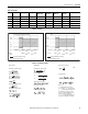
Figure 21 - Accuracy
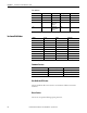
Figure 22 - Calculation Formulas
36 kVARh (+) X X X X # X Partial
37kWh (-) X XX XXXTotal
38 kVARh (-) X X X X # X Total
39 kWh (-) X X X X X X Partial
40 kVARh (-) X X X X # X Partial
Table 43 - Variables
No Variable 1-ph. Sys 2-ph. Sys 3-ph. 3/4-wire
Balanced Sys
3-ph. 2-wire
Balanced Sys
3-ph. 3-wire
Unbal. Sys
3-ph. 4-wire
Unbal. Sys
Notes
kWh, Accuracy (RDG) Depending on the Current
Percentage error limits for class index B
6A (I
max
)
6A (I
max
)
5A (I
n
)
5A (I
n
)
0.25A (I
tr
)
0.25A (I
tr
)
0.05A (I
min)
Accuracy limits (Real energy)
Start-up current: 5 mA
kVARh,Accuracy (RDG) Depending on the Current
Error
Accuracy limits (Reactive energy)
Start-up current: 5 mA
PF=1
PF=L0.5
or C0.8
6A (I
max
)
6A (I
max
)
5A (I
n
)
5A (I
n
)
0.25A
0.5A
0.1A
0.25A
sin ϕ =1
sin ϕ =0.5
+1.0%
0%
+1.5%
-1.0%
-1.5%
+2.0%
0%
+2.5%
-2.0%
-2.5%
System variables
Equivalent three-phase voltage
V oltage asymmetry
Three-phase real power
Three-phase reactive power
Three-phase apparent power
Phase variables
Instantaneous eective voltage
Instantaneous real power
Instantaneous power factor
Instantaneous eective current
Instantaneous apparent power
Instantaneous reactive power
Energy metering
Where:
i= considered phase (L1, L2 or L3)
P = real power; Q = reactive power;
t
1
,t
2
=starting and ending time points
of consumption recording; n = time
unit; Δ t= time interval between two
successive power consumptions;
n
1
,n
2
= starting and ending discrete
time points of consumption recording
Three-phase power factor
(TPF)
LL
LLLL
LL
V
VV
ASY
)(
minmax
LN
LNLN
LN
V
VV
ASY
)(
minmax