
Owner manual


66 Rockwell Automation Publication 1420-UM001D-EN-P - September 2013
Appendix B Technical Specifications
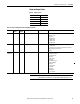
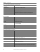
Data (bidirectional)
Dynamic (reading only) System and phase variables: see the Modbus register tables
Static (reading and writing only) All the configuration parameters; see the Modbus register tables
Data format 1 start bit, 8 data bit, no/even/odd parity,1 stop bit
Communication rate Selectable:9.6, 19.2, 38.4, 115.2 Kbps
Note With the rotary switch (on the back of the basic unit) in lock position, modification of programming parameters and reset
command by means of serial communication are not allowed. In this case just data reading is allowed
Insulation See Table 42
Isolation Between Inputs and Outputs (1 minute)
Table 36 - Serial RS-485/RS-232 Communication Specifications (485 option)
Attribute Value
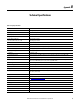
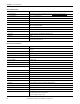
Table 37 - Energy Meters
Attribute Value
Meters
Total 4 (9+1 digit)
Partial 4 (9+1 digit)
Pulse output Connectable to total and/or partial meters
Energy meter recording Storage of total and partial energy meters. Energy meter storage format (EEPROM)
Min. -9,999,999,999.9 kWh/kVARh
Max. 9,999,999,999.9 kWh/kVARh
Energy meters
Total energy meters +kWh, +kVARh, -kWh, -kVARh
Partial energy meters +kWh, +kVARh, -kWh, -kVARh
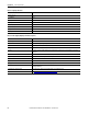
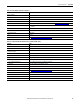
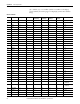
Table 38 - Display, Status Indicators, and Commands
Attribute Value
Display refresh time 100 ms
Display 4 lines, 4-DGT, 1 lines, 10-DGT
Type LCD, single color backlight
Digit dimensions 4-DGT: h 9.5 mm; 10-DGT: h 6.0 mm
Instantaneous variables read-out 4-DGT
Energy variables read-out Imported Total/Partial: 9+1DGT or 10DGT;
Exported Total/Partial: 9+1DGT or 10DGT (with ‘-’ sign)
Run hours counter 8+2 DGT (99.999.999 hours and 59 minutes max)
Overload status EEEE indication when the value being measured is exceeding the ‘Continuous inputs overload’ (max measurement
capacity)
Max and min indication Max instantaneous variables: 9999; energies: 9 999 999 99.9 or 9 999 999 999.
Min instantaneous variables: 0.000; energies 0.0
Front position status indicators
Virtual alarms 4 red status indicators available in case of virtual alarm (AL1-AL2- AL3-AL4).
Note that the real alarm is just the activation of the proper static or relay output if the proper module is available
Energy consumption Red status indicator (only kWh)