
Owner manual


Rockwell Automation Publication 1420-UM001D-EN-P - September 2013 45
Appendix A
PowerMonitor 500 Unit Data Tables
Summary of Data Tables
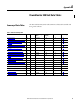
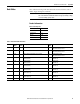
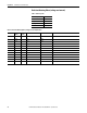
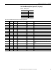
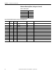
The Data Table Summary Index table summarizes all data tables available and
their general attributes.
Table 6 - Data Table Summary Index
Name of Data Table Read Write Modbus Starting
Address
CIP Assy. Instance ID
(decimal)
No. of Elements Refer to Page
Product Information
X 300001
(1)
100 10 47
Real-time Metering Values (voltage and current) X 300081 101 12 48
Real-time Metering Values (power, PF,
frequency)
X 300105 102 18 49
Maximum Metering Values (voltage and current) X 300337 103 12 50
Maximum Metering Values (power, PF,
frequency)
X 300361 104 17 51
DMD Metering Values (voltage and current) X 300849 105 12 52
DMD Metering Values (power, PF, frequency) X 300873 106 17 53
Total and Partial Energy Meters - EtherNet/IP
Data Table
X 301281 107 9 54
Configuration - Base Unit: Read and Write X X 304097 - 79 55
Configuration - Alarms X X Varies - 16 56
Configuration - RS-485/RS-232 Communication X X 304356 - 17 56
Configuration - Analog Outputs: Read and Write X X 304609 - 32 57
Analog Output Configuration Parameters X X Varies - 16 57
Configuration - Digital Outputs: Read and Write X X 304865 - 12 58
Commands: Write-only X 312369 - 45 59
Alarm and Output Status X 316385 108 2 61
(1) To obtain the physical address, subtract 300001 from the Modbus address and convert the result to hexadecimal. Example: Physical address 0x000B corresponds to Modbus address 300012.