
Owner manual


Rockwell Automation Publication 1420-UM001D-EN-P - September 2013 35
Chapter 4
Communication
EtherNet/IP Communication
EtherNet/IP communication is supported in PowerMonitor 500 units ordered
with optional Ethernet communication. Communication parameters in the
power monitor must be configured. Refer to Unit Configuration
on page 23.
The PowerMonitor 500 unit provides nine assembly instances containing real-
time, maximum, demand, energy, and status data that can be read by a client by
using implicit messaging (Class 1) or explicit messaging (Class 3 or UCMM).
Appendix A
lists the assembly instances, sizes, data types, and other details. The
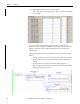
power monitor returns EtherNet/IP data as little-endian, the same byte order
used in the Logix family of programmable controllers.
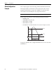
Figure 20 - Byte Order Example
The power monitor supports the following communication commands:
• CIP Generic Assembly Object (Class 04), Get_Attribute_Single (service
code 0x0E) for Attribute 3 (data)
• CIP Generic Assembly Object (Class 04), Get_Attribute_Single (service
code 0x0E) for Attribute 4 (size in bytes)
Refer to Appendix C
for additional information on the EtherNet/IP
communication implementation in the PowerMonitor 500 unit.
TIP
The Ethernet hardware address (MAC ID) is printed on the unit label.
IMPORTANT
The power monitor does not support configuration or commands on
EtherNet/IP network. To write the configuration of command data, refer to the
section on Modbus Communication
on page 41.
15 14 13 12 11 10 9 8 7 6 5 4 3 2 1 0
MSb (Most Signicant Bit) (Least Signicant Bit) LSb
Word
Low Byte (LSB)
High Byte (MSB)