
Owner manual


Rockwell Automation Publication 1420-UM001D-EN-P - September 2013 21
Installation and Wiring Chapter 2
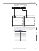
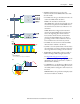
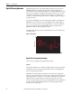
Figure 18 - Optional Ethernet Communication (ENT option)
The PowerMonitor 500 unit connects to industry-standard Ethernet hubs and
switches by using standard CAT-5 UTP (unshielded twisted-pair) cables with
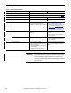
RJ45 connectors. Table 3
shows the cable and connector pin assignments.
Ethernet Network Switch Uplink to LAN
PowerMonitor 500 PowerMonitor 500
Table 3 - Ethernet Network Connections
Terminal Signal
1TX+
2TX-
3RX+
4
5
6RX-
7
8