
Owner manual


Rockwell Automation Publication 1420-UM001D-EN-P - September 2013 17
Installation and Wiring Chapter 2
Wiring Diagrams
The wiring diagrams in this manual are drawn with European (IEC) conventions.
For convenience, a connection diagram is shown below in IEC style on the left
and in its corresponding NEMA style (used in the U.S.) on the right.
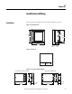
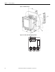
Figure 7 - Wiring Diagram Interpretation
These diagrams are simplified. Wiring of the power monitor must comply with
all applicable codes, standards, and regulations. Voltage and control power wiring
must be protected by suitable overcurrent protection. Connect current
transformer (CT) secondary wiring through a suitable shorting terminal block.
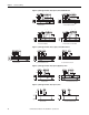
Figure 8 - System Type Selection: 3-phase.2, 3-phase, 2-wire, Balanced Load
Figure 9 - System Type Selection: 3-phase.n, 3-phase, 4-wire, Unbalanced Load
IMPORTANT
In these diagrams, ‘balanced load’ configurations permit 3-phase
measurement by using only one phase connection. Unbalance in the measured
circuit impacts the accuracy of the measurements.
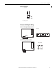
1-CT and 1-VT/PT Connections
1-CT Connection
I1
I1
L1 N S1 S2
L1 N S1 S2
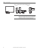
3-CT and 3-VT/PT Connections
3-CT Connection
I1 I2 I3
I1 I2 I3
L2L1 L3 N S1S1 S2S2 S1 S2
L2L1 L3 N S1S1 S2S2 S1 S2