
Owner manual


Rockwell Automation Publication 1420-UM001D-EN-P - September 2013 13
PowerMonitor 500 Overview Chapter 1
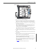
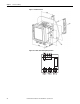
Display Icons
9. Indicates that the metering values displayed are system (three-phase)
values.
10. Indicates a phase sequence error alarm.
11. Configuration lock switch is not active. Always indicates unlocked.
12. Indication of serial RS-485/RS-232 data transmission (TX) and reception
(RX).
Alarm Icons
• Indicates a high value alarm
• Indicates a low value alarm
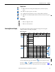
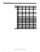
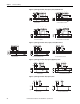
Selecting Data to Display
The table below provides a guide to navigation through the metering data
displays available on the front panel display.
To access information pages, press and hold for more than 2 seconds,
then press and to select information items, as shown in Ta b le 2
.
Information items are not displayed for options that are not installed.
9
10
11
12
Table 1 - Navigation
No. Line 1 Line 2 Line 3 Line 4 Line 5 Note
Press the
key
for <2
seconds
0 Home page Programmable
1 Total kWh (+) Depending on the last displayed page of
instantaneous variables.
2Total kVARh
(+)
3 kWh (+) part.
4 kVARh (+)
part.
5 Run Hours
(99999999.99)
Press the
key
for <2
seconds
6 Phase seq. VLN VL1 VL2 VL3
7 Phase seq. VLN VL1-2 VL2-3 VL3-1
8 Phase seq. An AL1 AL2 AL3
9Phase seq.Hz---
10 Phase seq. VA VA L1 VA L2 VA L3
11 Phase seq. var var L1 var L2 var L3
12 Phase seq. W WL1 WL2 WL3
13 Phase seq. PF PF L1 PF L2 PF L3