User Manual PowerMonitor 500 Unit Catalog Numbers 1420
Important User Information Read this document and the documents listed in the additional resources section about installation, configuration, and operation of this equipment before you install, configure, operate, or maintain this product. Users are required to familiarize themselves with installation and wiring instructions in addition to requirements of all applicable codes, laws, and standards.
Summary of Changes This manual contains new and updated information. Changes throughout this revision are marked by change bars, as shown to the right of this paragraph. New and Updated Information This table contains the changes made to this revision.
Summary of Changes Notes: 4 Rockwell Automation Publication 1420-UM001D-EN-P - September 2013
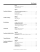
Table of Contents Preface Catalog Number Explanation . . . . . . . . . . . . . . . . . . . . . . . . . . . . . . . . . . . . . . . 7 Additional Resources . . . . . . . . . . . . . . . . . . . . . . . . . . . . . . . . . . . . . . . . . . . . . . . 7 Chapter 1 PowerMonitor 500 Overview About the PowerMonitor 500 Unit . . . . . . . . . . . . . . . . . . . . . . . . . . . . . . . . . 9 PowerMonitor 500 Features and Functions . . . . . . . . . . . . . . . . . . . . . . . . . . 9 Front Panel Features . . . . .
Table of Contents Index 6 Assembly Object Instances . . . . . . . . . . . . . . . . . . . . . . . . . . . . . . . . . . . . . . . . 77 Technical Notes. . . . . . . . . . . . . . . . . . . . . . . . . . . . . . . . . . . . . . . . . . . . . . . . . . 78 . . . . . . . . . . . . . . . . . . . . . . . . . . . . . . . . . . . . . . . . . . . . . . . . . . . . . . . . . . . . . . . . .
Preface Catalog Number Explanation 1420 Bulletin Number 1420 - PowerMonitor 500 -V1 Voltage V1 - 240V AC V-LL 120V AC V-LN/208V AC V-LL V2 - 400V AC V-LN and 690V AC V-LL Additional Resources P -485 Auxiliary P - Pulse (Digital) Output A - Analog Output Blank - No Output A Optional Comms 485 - Serial RS-232, RS-485, Modbus RTU ENT - EtherNet/IP and Modbus TCP Blank - No Comm Series A These documents contain additional information concerning related products from Rockwell Automation.
Preface Notes: 8 Rockwell Automation Publication 1420-UM001D-EN-P - September 2013
Chapter 1 PowerMonitor 500 Overview About the PowerMonitor 500 Unit The PowerMonitor 500 unit is an AC power monitor with a built-in advanced configuration system and LCD data display. The unit is designed for measurement of electrical parameters in a variety of three-phase and single-phase circuits. The unit is enclosed in a modular housing for panel mounting, with IP65 degree of protection in front of the panel. The power monitor can be provided with analog or digital outputs.
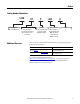
Chapter 1 PowerMonitor 500 Overview • • • • • • • • • • • • • • • • Front Panel Features Up to four configurable virtual alarms Class 1 (kWh) according to EN62053-22 Class B (kWh) according to EN50470-3 Class 2 (kVARh) according to EN62053-23 Accuracy ±0.5% of reading (current/voltage) Metering values display: 4 lines x 4 digit Energy value display: 10 digit plus sign Three-phase (system) variables: V(L-L), V(L-N), A, VA, W, VAR, power factor, frequency, unbalance.
PowerMonitor 500 Overview Chapter 1 Figure 1 - Front Panel 3 4 5 1 6 2 PowerMonitor 500 1. Active Alarms AL1…AL4 status indicators. 2. Real Energy consumption rate status indicator. Faster flashing indicates higher rate of consumption. Maximum frequency 16 Hz per EN5047-1. 3. Exit Button - Press quickly to exit submenus, or to exit the programming menus in Programming mode. When in the programming menu, press and hold the Exit button for at least 2 seconds to exit the programming menu.
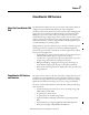
Chapter 1 PowerMonitor 500 Overview Additional Button Functions Certain buttons have two functions. To access the second function, press and hold the button for more than 2 seconds. Displays PowerMonitor 500 information screens, which provide reference standards, firmware revision, and year of manufacture. Resets the MAX (maximum) of the displayed variables. Resets the dmd (demand) of the displayed variables. To perform a reset, press this button to confirm.
Chapter 1 PowerMonitor 500 Overview Display Icons 9 10 9. Indicates that the metering values displayed are system (three-phase) values. 10. Indicates a phase sequence error alarm. 11. Configuration lock switch is not active. Always indicates unlocked. 11 12 12. Indication of serial RS-485/RS-232 data transmission (TX) and reception (RX).
Chapter 1 PowerMonitor 500 Overview Table 2 - Information Items No. Line 1 Line 2 Line 3 Line 4 Line 5 1 Lot n. xxxx Yr. xx rEL A.01 1…60 (min) ‘dmd’ 2 Conn. xxx.x (3ph.n/3ph/ 3ph./ 3ph.2/1ph/2ph) CT.rA 1.0…99.99k Pt.rA 1.0…9999 3 LED PULSE kWh 0.001…1000 kWh per pulse 4 PULSE OUT1 kWh/kVARh(1) 0.
Chapter 2 Installation and Wiring Installation This section shows the dimensions of the unit for installation in a panel. Figure 2 - Base Unit Dimensions 89.97 mm (3.54 in.) 93.00 mm (3.66 in.) 96.00 mm (3.78 in.) 96.00 mm (3.78 in.) 20.20 mm 29.70 mm (0.80 in.) (1.17 in.) Figure 3 - Panel Cut-out 91.00 mm (3.58 in.) Figure 4 - Factory-installed Optional Modules Serial and Ethernet Communication Modules Digital and Analog Output Modules 62.99 mm (2.48 in.) 89.49 mm (3.52 in.) 62.99 mm (2.
Chapter 2 Installation and Wiring Figure 5 - Installation in Panel Figure 6 - Rear View of Unit Showing Wiring Terminals Power Supply 16 Rockwell Automation Publication 1420-UM001D-EN-P - September 2013
Chapter 2 Installation and Wiring Wiring Diagrams The wiring diagrams in this manual are drawn with European (IEC) conventions. For convenience, a connection diagram is shown below in IEC style on the left and in its corresponding NEMA style (used in the U.S.) on the right. Figure 7 - Wiring Diagram Interpretation These diagrams are simplified. Wiring of the power monitor must comply with all applicable codes, standards, and regulations.
Chapter 2 Installation and Wiring Figure 10 - System Type Selection: 3-Ph, 3-phase, 3-wire, Unbalanced Load I1 I2 I1 I3 L1 L2 L3 N S1 S2 S1 S2 S1 S2 I2 I3 L1 L2 L3 N S1 S2 S1 S2 S1 S2 3-CT and 2-VT/PT Connections 3-CT Connection I1 I2 I1 I3 I2 I3 L1 L2 L3 N S1 S2 S1 S2 S1 S2 L1 L2 L3 N S1 S2 S1 S2 S1 S2 2-CT Connections (ARON) 2-CT and 2-VT/PT Connections ARON Figure 11 - System Type Selection: 3-Ph.
Chapter 2 Installation and Wiring Figure 14 - Supply Power 90…260V AC/DC 1 2 + F = 250V (T) 630 mA Factory Installed Option Wiring Figure 15 - Pulse (digital) Outputs (P option) Opto-mosfet 1 Out 1 2 3 4 5 6 7 8 Out 2 Out 1 Out 2 Figure 16 - Analog Outputs (A option) Analog 20 mA DC Out 1 t1 Ou t2 Ou Rockwell Automation Publication 1420-UM001D-EN-P - September 2013 1 2 Out 2 3 4 19
Chapter 2 Installation and Wiring Figure 17 - Serial RS-485 and RS-232 Communication Wiring (485 option) RS-485 Port RS-232 Port 8 8 8 7 7 7 6 6 6 4 4 4 3 3 3 2 2 2 1 1 1 IMPORTANT 20 Mandatory Termination Additional devices provided with RS-485 are connected in parallel. The termination of the serial output is carried out only on the last instrument of the network, by means of a jumper between (B+) and (T).
Installation and Wiring Chapter 2 Figure 18 - Optional Ethernet Communication (ENT option) Ethernet Network Switch Uplink to LAN PowerMonitor 500 PowerMonitor 500 The PowerMonitor 500 unit connects to industry-standard Ethernet hubs and switches by using standard CAT-5 UTP (unshielded twisted-pair) cables with RJ45 connectors. Table 3 shows the cable and connector pin assignments.
Chapter 2 Installation and Wiring Notes: 22 Rockwell Automation Publication 1420-UM001D-EN-P - September 2013
Chapter 3 Unit Configuration Configure with the Display The PowerMonitor 500 unit provides menu-based configuration (programming) by using its front panel display. The programming menus let you select parameters to edit, select digits within parameters, and increase or decrease the value of each digit. Place the unit in Programming mode by pressing Program/select (8) for about 2 seconds. The front panel displays the PASSWORD? menu page 0 in Editing mode.
Chapter 3 Unit Configuration Table 4 - Front Panel Display Descriptions Display Item Description Navigating Menus 1 Programming mode indicator Indicates programming mode. 2 Programming menu page Identifies the current programming menu page. Refer to the programming flow chart beginning on page 26. 3 Editing mode indicator Does not appear. Indicates the parameter being edited. 4 Cursor Does not appear. Appears beneath the digit currently being edited.
Unit Configuration Chapter 3 Editing Decimal Point and Multiplier When the cursor is beneath the last digit on the left, pressing Exit (6) lets you change the decimal point and the multiplier (9) (k or M). The blinking ‘dP’ (decimal point) text (10) indicates this capability. 9 10 To modify the decimal point position and the multiplier, use the Up and Down arrow (7) to select the desired value.
Chapter 3 Unit Configuration Configuration Flow Chart • 10 CHANGE PAS: this function lets you modify the PASS value with a new value (from 0…9999). • 20 BACKLIGHT: adjusts backlight time from 0…255 minutes (0 = always on). • 50 SYSTEM: this function lets you select the type of electrical system. Refer to pages 17…18 for descriptions and wiring diagrams corresponding to the system type designations, such as, 3P and 3P.n.
Unit Configuration • 80 DMD: This function lets you select the calculation method of the DMD/AVG value of the selected variable. – 81 TYPE: select the type of Calculation mode to be used for the DMD/AVG calculation. FIXED: The instrument calculates the AVG/DMD value of the measured variable over the selected interval, updates the AVG/DMD value at the end of the interval, then resets and starts a new calculation.
Chapter 3 Unit Configuration • 120 RS232-485: User settings for the RS-232 and RS-485 serial communication ports. • 130 ETHERNET: User settings for the Ethernet communication port. -IP ADDRESS www.xxx.yyy.zzz -SUBNET www.xxx.yyy.zzz ETHERNET -GATEWAY www.xxx.yyy.
Unit Configuration L ist of available variables As AN OUT 1 Save the set parameters and come back to the measuring mode. Chapter 3 • 210 AN OUT 1: User programming of the analog outputs (0…20 mA). – 211 VARIABLES: selects the variable to be retransmitted by means of the analog output. – 212 MIN INPUT: minimum value of the variable input range, corresponds to the ‘MIN OUTPUT’ value of the analog output.
Chapter 3 Unit Configuration Digital Filtering Operation Digital filtering smooths out the display of fluctuating values. The parameter FILTER S defines the operating range of the filter. This operating range is represented as a yellow band (each small square is one digit). While the measured value (red curve in figure) is within this band, the filter is active. Once the value exceeds the operating range, the filter is deactivated and a new band is active around the new value.
Unit Configuration Chapter 3 FILTER CO: if the new value measured by the instrument is within the action range of the filter, the new displayed value is obtained by adding algebraically the previous value to the variation divided by the filtering coefficient. As a consequence, a value higher than this coefficient implies a longer settling time and therefore a better stability.
Chapter 3 Unit Configuration FILTER CO: if the new value acquired by the unit is within the filtering action range, the new displayed value is obtained by adding algebraically the previous value to the variation divided by the filtering coefficient. As a consequence, a value higher than this coefficient implies a higher settling time and therefore better stability.
Unit Configuration Analog Output Configuration Examples Chapter 3 These examples apply to units with catalog numbers 1420-V1A and 1420-V2A. Example 1: Power value retransmission by means of a 0…20 mA analog output. This example describes how to retransmit measured consumed power up to 100 kW by means of a 4…20 mA signal. Program the unit as follows: • VARIABLE: W (system real power) • MIN OUT: 20.0% means 4 mA.
Chapter 3 Unit Configuration Alarm Configuration Example These examples apply to units with catalog numbers 1420-V1P and 1420-V2P. This example describes an alarm when a measured real power value exceeds a programmed threshold. For example, when 300 kW are exceeded, the alarm occurs and the load controlled by the relay output is disconnected. IMPORTANT The PowerMonitor 500 unit is not intended to be applied as a protective device. An ‘UP’ alarm is selected.
Chapter 4 Communication EtherNet/IP Communication EtherNet/IP communication is supported in PowerMonitor 500 units ordered with optional Ethernet communication. Communication parameters in the power monitor must be configured. Refer to Unit Configuration on page 23. TIP The Ethernet hardware address (MAC ID) is printed on the unit label.
Chapter 4 Communication Electronic Data Sheet (EDS) The EDS file is used to convey device configuration data that is provided by the manufacturer. You can obtain EDS files for the PowerMonitor 500 unit by downloading the file from the following website: http://www.rockwellautomation.com/rockwellautomation/support/networks/eds.
Communication Chapter 4 We assume that you are familiar with basic message programming in a Logix controller. Once you have set up the logic, message tag, destination tag, and message instruction, follow these steps to configure the message. This example uses a CompactLogix controller, revision 20. 1. Choose the appropriate parameters in the Message Configuration window. Parameter Choice Message Type Choose message type CIP Generic.
Chapter 4 Communication 2. Click the Communication tab and enter the path and method. 3. Click OK to complete message setup. Path Method CIP Implicit Messaging - Generic Ethernet Module Input Data Connection The PowerMonitor 500 unit with EtherNet/IP communication supports Class 1 connections to its nine assembly instances.
Communication Chapter 4 4. Enter the setup parameters as listed in this dialog box and explained in Table 5.
Chapter 4 Communication 5. When finished, click OK to save the new module. The module updates its input tag .I.Data at the Requested Packet Interval (RPI). You can use additional programming to show the data in a different way. Instances 101…107 show data in the REAL, or floating point, format. However, Instance 100 (shown above) combines ASCII characters with numeric byte (SINT) values.
Communication Chapter 4 The destinations of the CPS instructions are in a tag with a user-defined data type. The destination tag shows the data in this way. Modbus Communication For a complete description of the MODBUS protocol refer to the following documents that can be downloaded from http://www.modbus.
Chapter 4 Communication The PowerMonitor 500 unit supports the following Modbus functions: • 0x03 - Read n Holding Registers • 0x04 - Read n Input Register • 0x06 - Write one Holding Register • 0x10 - Write multiple registers • 0x08 - Diagnostic (with sub-function code 0x00) • 0x42 - Read n Special Registers (vendor specific) • Broadcast mode (write command on address 00h) In this section, Modbus addresses are indicated in two ways.
Communication Chapter 4 Modbus Register Format Modbus registers are 16-bit words organized as shown in the following diagram. Holding Register (word) High Byte (MSB) 15 14 13 12 11 10 MSb (Most Significant Bit) Low Byte (LSB) 9 8 7 6 5 4 3 2 1 0 (Least Significant Bit) LSb 32-bit and 64-bit data types presented as arrays of single registers in LSW (least significant word) to MSW (most significant word) order.
Chapter 4 Communication Notes: 44 Rockwell Automation Publication 1420-UM001D-EN-P - September 2013
Appendix A PowerMonitor 500 Unit Data Tables Summary of Data Tables The Data Table Summary Index table summarizes all data tables available and their general attributes. Table 6 - Data Table Summary Index Name of Data Table Read Write Modbus Starting Address CIP Assy. Instance ID (decimal) No.
Appendix A PowerMonitor 500 Unit Data Tables Geometric Representation of Power and Power Factor Power and power factor values are signed values in accordance with EN 62053 and as indicated in the diagram. Inductive or lagging power factor (Quadrant I and III) is indicated by a positive power factor value. Capacitive or leading power factor is indicated by a negative value.
PowerMonitor 500 Unit Data Tables Data Tables Appendix A These tables detail each specific data table and its associated elements, such as address, length, description, and format. IMPORTANT In the data tables, the symbol is used to indicate 3-phase or system values. The context determines whether this indicates average (for example, voltage) or total (for example, power) values. Product Information Table 7 - Table Properties CIP Assembly Instance 100 No.
Appendix A PowerMonitor 500 Unit Data Tables Real-time Metering Values (voltage and current) Table 9 - Table Properties CIP Assembly Instance 101 No.
PowerMonitor 500 Unit Data Tables Appendix A Real-time Metering Values (power, PF, frequency) Table 11 - Table Properties CIP Assembly Instance 102 No.
Appendix A PowerMonitor 500 Unit Data Tables Maximum Metering Values (voltage and current) Table 13 - Table Properties CIP Assembly Instance 103 No.
PowerMonitor 500 Unit Data Tables Appendix A Maximum Metering Values (power, PF, frequency) Table 15 - Table Properties CIP Assembly Instance 104 No.
Appendix A PowerMonitor 500 Unit Data Tables DMD Metering Values (voltage and current) Table 17 - Table Properties CIP Assembly Instance 105 No.
PowerMonitor 500 Unit Data Tables Appendix A DMD Metering Values (power, PF, frequency) Table 19 - Table Properties CIP Assembly Instance 106 No.
Appendix A PowerMonitor 500 Unit Data Tables Total and Partial Energy Meters - EtherNet/IP Data Table Table 21 - Table Properties CIP Assembly Instance 107 No. of Elements 18 Length in Words 36 Data Type REAL Data Access Read Only Table 22 - Total and Partial Energy Meters - EtherNet/IP Data Table Element Length (words) Description / Units Data Format Notes 0 2 Total kWh+ REAL Range 0.0 … 999,999.999 1 2 Total GWh+ REAL Range 0 … 9,999,999 2 2 Total kVARh+ REAL Range 0.
PowerMonitor 500 Unit Data Tables Appendix A Table 23 - Energy Metering Values Modbus - Read-only Modbus Address Length (words) Description / Units Data Format Notes 301281 4 Total kWh+ ULINT Values in Wh or varh 301285 4 Total kVARh+ ULINT 301289 4 Total kWh- ULINT 301293 4 Total kVARh- ULINT 301297 4 Partial kWh+ ULINT 301301 4 Partial kVARh+ ULINT 301305 4 Partial kWh- ULINT 301309 4 Partial kVARh- ULINT 301313 4 Hours counter ULINT Hours value: integer part go
Appendix A PowerMonitor 500 Unit Data Tables Table 25 - Configuration - Alarms Modbus Address Length (words) Description / Units Data Format Notes Block address 1 +0 Alarm N - Enabling UINT Value=1: alarm N enabled Value=0: alarm N disabled All other values are considered as value=0 Block address 1 +1 Alarm N - Variable type to be linked to UINT Refer to the Connected Variable List (Table 43) Block address 1 +2 Alarm N - Delay ON activation (s) UINT Value min=0 Value max=3600 If the set va
PowerMonitor 500 Unit Data Tables Appendix A Table 27 - Configuration - Analog Outputs: Read and Write Modbus Address Length (words) Description / Units Data Format Notes 304609 16 Analog output A0: parameters configuration CUSTOM Refer to Table 28 304625 16 Analog output A1: parameters configuration CUSTOM Table 28 - Analog Output Configuration Parameters Modbus Address Length (words) Description / Units Data Format Block address +0 1 Type of the variable that is linked to the N analo
Appendix A PowerMonitor 500 Unit Data Tables Table 29 - Configuration - Digital Outputs: Read and Write Modbus Address Length (words) Description / Units Data Format Notes 304865 1 Digital output channel 1: enabling UINT 0=Remote 1=Alarm 2= Pulse 304866 1 Digital output channel 1: output working mode UINT 0=NO 1=NC (only if selected ‘Alarm’ type) 304867 1 Digital output channel 1: linked alarm UINT 0=AL1 1=AL2 2=AL3 3=AL4 (only if selected ‘Alarm’ type) 304868 1 Channel 1: linked cou
PowerMonitor 500 Unit Data Tables Appendix A Table 30 - Commands: Write-only Modbus Address Length (words) Description / Units Data Format Notes 312369 1 Get clock values UINT Value=1 - command executed; Value1 - no effect 312370 1 Set clock values UINT Value=1 - date and time set 312374 1 Enable optional pulse (digital) outputs UINT Value=1 - module enabled; Value=0 - module disabled 312376 1 Enable optional serial communication UINT Value=1 - module enabled; Value=0 - module dis
Appendix A PowerMonitor 500 Unit Data Tables Table 30 - Commands: Write-only Modbus Address Length (words) Description / Units Data Format Notes 312814 1 Reset W L1 UINT 16 312815 1 Reset W L2 UINT 16 Bit0 = 1: Reset Max Value Bit1 = 1: Reset DMD value Bits 2 … 15: Reserved 312816 1 Reset W L3 UINT 16 312817 1 Reset W UINT 16 312818 1 Reset VA L1 UINT 16 312819 1 Reset VA L2 UINT 16 312820 1 Reset VA L3 UINT 16 312821 1 Reset VA UINT 16 ?312822 1 Reset VAR L1 U
PowerMonitor 500 Unit Data Tables Appendix A Alarm and Output Status Table 31 - Table Properties CIP Assembly Instance 108 No.
Appendix A PowerMonitor 500 Unit Data Tables Notes: 62 Rockwell Automation Publication 1420-UM001D-EN-P - September 2013
Appendix B Technical Specifications Table 33 - Input Specifications Attribute Value Rated inputs System type: 1, 2, or 3-phase Current type Galvanic insulation by means of built-in CTs Current range (by CT) 5 A nom (6 A max) Voltage (by direct connection or VT/PT) V1: 120/208V LL; V2: 400/690V LL Accuracy (Display and RS-485) (@25 °C ±5 °C, R.H.
Appendix B Technical Specifications Table 33 - Input Specifications Attribute Value Voltage overloads Continuous 1.2 Un For 500 ms 2 Un Input impedance 400VL-L (V2) > 1.6 M 208VL-L (V1) > 1.6 M 5(6)A < 0.2 VA Frequency 40…440 Hz Table 34 - Pulse (digital) Output Specifications (P option) Attribute Value Physical outputs 2 Purpose For either alarm output or digital output Type Relay, SPDT type AC 1-5 A @ 250V AC; AC 15-1.5 A @ 250V AC DC 12-5A @ 24V DC; DC 13-1.
Technical Specifications Appendix B Table 35 - Analog Output Specifications (A option) Attribute Value Number of outputs 2 Accuracy (@ 25 °C ±5 °C, R.H. 60%) ± 0.2% of full scale Range 0…20 mA Configuration By means of the front keypad Signal retransmission The signal output can be connected to any instantaneous variable.
Appendix B Technical Specifications Table 36 - Serial RS-485/RS-232 Communication Specifications (485 option) Attribute Value Data (bidirectional) Dynamic (reading only) System and phase variables: see the Modbus register tables Static (reading and writing only) All the configuration parameters; see the Modbus register tables Data format 1 start bit, 8 data bit, no/even/odd parity,1 stop bit Communication rate Selectable:9.6, 19.2, 38.4, 115.
Technical Specifications Appendix B Table 38 - Display, Status Indicators, and Commands Attribute kWh pulsating Value 0.001 kWh/kVARh by pulse if the Ct ratio by VT ratio is 7 0.01 kWh/kVARh by pulse if the Ct ratio by VT ratio is 7.1 70.0 0.1 kWh/kVARh by pulse if the Ct ratio by VT ratio is 70.1 700.0 1 kWh/kVARh by pulse if the Ct ratio by VT ratio is 700.1 7000 10 kWh/kVARh by pulse if the Ct ratio by VT ratio is 7001 70.00k 100 kWh/kVARh by pulse if the Ct ratio by VT ratio is >70.
Appendix B Technical Specifications Table 39 - Main Functions Attribute Value Controlled variables The alarms can be connected to any instantaneous variable. See List of Connectable Variables on page 69 Set-point adjustment From 0…100% of the display scale Hysteresis From 0 to full scale On-time delay 0…9999s Response time, min 200 ms, filters excluded. Set-point on-time delay: ‘0 s’ Reset By means of the front keypad.
Technical Specifications Appendix B Table 40 - General Specifications Attribute Value Housing DIN Dimensions (WxHxD) Module holder: 96 x 96 x 50 mm ‘A’ and ‘B’ type modules: 89.5 x 63 x 16 mm ‘C’ type module: 89.5 x 63 x 20 mm Depth behind panel, max 81.
Appendix B Technical Specifications (X) = available; (O) = not available (variable not available on the display); (#) Not available (the relevant page is not displayed) (1) Max value with data storage Table 43 - Variables No Variable 1-ph. Sys 2-ph. Sys 3-ph. 3/4-wire Balanced Sys 3-ph. 2-wire Balanced Sys 3-ph. 3-wire Unbal. Sys 3-ph. 4-wire Unbal.
Technical Specifications Appendix B Table 43 - Variables No Variable 1-ph. Sys 2-ph. Sys 3-ph. 3/4-wire Balanced Sys 3-ph. 2-wire Balanced Sys 3-ph. 3-wire Unbal. Sys 3-ph. 4-wire Unbal.
Appendix B Technical Specifications Notes: 72 Rockwell Automation Publication 1420-UM001D-EN-P - September 2013
Appendix C PowerMonitor 500 EtherNet/IP Device Profile This section describes the specific CIP Objects, Instances, Attributes, and Services supported by the PowerMonitor 500 system. This information is for anyone wishing to integrate the PowerMonitor 500 system into existing or planned shop floor networks. General For this device profile, we use a PowerMonitor 500 unit and an EtherNet/IP communication module to provide power and energy metering data via an EtherNet/IP network.
Appendix C PowerMonitor 500 EtherNet/IP Device Profile Class Attributes Instance Attributes Attr ID Access Name Data Type Default Value 0x01 Get Revision UINT 1 0x02 Get Max Instance UINT 1 0x03 Get Number of Instances UINT 1 0x06 Get Maximum ID Number Class Attributes UINT 7 0x07 Get Maximum ID Number Instance Attributes UINT 7 Attr ID Access Name Data Type 0x01 Get Vendor ID UINT 0x02 Get Device Type UINT 0x03 Get Product Code UINT 0x04 Get Revision Str
PowerMonitor 500 EtherNet/IP Device Profile Appendix C Request Parameters Parameter Data Type Type Description USINT Type of Reset to perform Reset Types The type of Reset requested can be any of the following. Value Name Description 0 Power-Cycle Emulate as closely as possible cycling power on the item the Identity Object represents. 1 Power-Cycle Emulate as closely as possible cycling power on the item the Identity Object represents.
Appendix C PowerMonitor 500 EtherNet/IP Device Profile Instance 1 Attribute Values Attr ID Name Value 0x01 Vendor ID 1 (Rockwell Automation) 0x02 Device Type 0x92 (146d) 0x03 Product Code See table below 0x04 Revision Dynamic (varies with the communication firmware revision) 0x05 Status Dynamic 0x06 Serial Number 940000000…950000000 0x07 Product Name PowerMonitor 500 Product Code Values Part Number Name Product Code Description 1420-V1-ENT 146 - PowerMonitor 500 4 PowerMonit
PowerMonitor 500 EtherNet/IP Device Profile Appendix C Class Attributes Attr ID Access Name Data Type Default Value 0x01 Get Revision UINT 2 0x02 Get Max Instance UINT 108d 0x03 Get Number of Instances UINT 9 0x04 Get Optional Attributes List STRUCT of UINT ARRAY of UINT 0x0001, {0x0004} 0x06 Get Maximum ID Number Class Attributes UINT 7 0x07 Get Maximum ID Number Instance Attributes UINT 4 Instance Attributes Attr ID Access Name Data Type Default Value All of the me
Appendix C PowerMonitor 500 EtherNet/IP Device Profile Connections The Assembly Object supports both scheduled (Class 1) and unscheduled connections (Class 3 and UCMM).
PowerMonitor 500 EtherNet/IP Device Profile Appendix C Modbus TCP The communication module supports Modbus TCP. The protocol is the same as the PowerMonitor 500 unit with RS485 (Modbus RTU). Refer to Chapter 4 for protocol details. In this product, only one Modbus TCP connection (1 socket) is allowed. The EtherNet/IP and Modbus TCP do not run concurrently. If Modbus TCP communication occurs, EtherNet/IP communication stops temporarily but recovers in a minute or two.
Appendix C PowerMonitor 500 EtherNet/IP Device Profile Notes: 80 Rockwell Automation Publication 1420-UM001D-EN-P - September 2013
Index Numerics 485 option 65 A A option 65 about PowerMonitor 500 9 access information pages 13 accuracy 10, 71 additional button functions 12 address Modbus 42 physical 42 alarm configuration 34 alarm icons 13 analog output specifications 65 analog outputs 19 configuration 33, 57 B billing 9 buttons 11 additional functions 12 descriptions 24 C calculation formulas 71 catalog number explanation 7 change decimal point 25 multiplier 25 CIP generic 36 class 1 38 comman specifications 66 commands 59 communi
Index front panel buttons 11, 24 indicators 11 functions 9 G general specifications 68 geometric representation 46 ground connection 42 I icons alarm 13 display 13 IEC vs NEMA diagrams 17 implicit messaging 38 indications 12 indicators 11 information access 13 information items 14 input specifications 63 installation 15, 16 IP65 9 isolation between inputs and outputs 69 L line amplifier 42 list of variables 69-71 load profiling 9 Logix Designer application 36 M main functions specifications 67 menu pag
Index S save changes 24 selecting data to display 13 serial communication specifications 65 shielded cable 42 single-phase 10 software RSEnergyMetrix 9 specifications 485 option 65 A option 65 analog output 65 command 66 digital output 64 display 66 energy meters 66 general 68 input 63 isolation between inputs and outputs 69 main functions 67 P option 64 power supply 69 pulse output 64 relay output 64 RS-485 and RS-232 65 serial communication 65 status indicators 66 status 61 status indicators specificatio
Index Notes: 84 Rockwell Automation Publication 1420-UM001D-EN-P - September 2013
Rockwell Automation Support Rockwell Automation provides technical information on the Web to assist you in using its products. At http://www.rockwellautomation.com/support you can find technical and application notes, sample code, and links to software service packs. You can also visit our Support Center at https://rockwellautomation.custhelp.com/ for software updates, support chats and forums, technical information, FAQs, and to sign up for product notification updates.