Temperature Rise Calculation Software – Tutorial In Accordance with the Calculation Method to IEC 60890
Temperature Rise Calculation Software (TRCS) Rockwell Automation All rights reserved. No parts of this work may be reproduced in any form or by any means – graphic, electronic or mechanical, including photocopying, recording, taping or information storage and retrieval systems – without the written permission of the publisher. Products that are referred to in this document may be either trademarks and/or registered trademarks of the respective owners.
Table of Contents Page Chapter 1 Temperature Rise Calculation Software (TRCS) – Tutorial 1.1 Chapter 2 The Tutorial Project . . . . . . . . . . . . . . . . . . . . . . . . . . . . . . . . . . . . . .2 Start with Your First TRCS Project 2.1 “Environmental Conditions” Tab . . . . . . . . . . . . . . . . . . . . . . . . . . .6 2.2 “Enclosure” Tab. . . . . . . . . . . . . . . . . . . . . . . . . . . . . . . . . . . . . . . . .8 2.3 Evaluation of Power Loss . . . . . . . . . . . . . . . . . . . . . . .
Chapter 1 Temperature Rise Calculation Software (TRCS) – Tutorial This tutorial will help you become familiar with the TRCS Temperature Rise Calculation Software. It will lead you through a sample project. Please consider this document as complementary information to the Help file and the User Manual, where you will find detailed information about particular topics. 1.1 The Tutorial Project It is strongly recommended to work through the MCS Star Tutorial first.
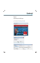
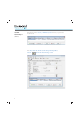
Chapter 2 Start with Your First TRCS Project Start the Temperature Rise Calculation Software (TRCS). In the startup window, select the [ New Project ] button. Enter the name of the project, then select the [ OK ] button. Select the menu item “Databases/Person in charge”.
Start with Your First Project In the following window, select the [ + Add Dataset ] button, then enter your personal data into the new row. (continued) In the “Project data” tab, enter the customer data per the example below. Select the 4 button in the “Person in charge” section.
Start with Your First Project If the data for “Customer” and “Person in charge” is already entered, it can be retrieved from the database by selecting the button in the corresponding area. (continued) Newly entered or amended data can be stored in the database by selecting the button. The data entry in the “Project data” tab is now complete. Please save your work before you go forward to the next tab.
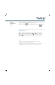
2.1 “Environmental Conditions” Tab Before you enter the environmental conditions, you may want to change some program settings, like units of measure or temperature. Select the menu option “Extra /Settings...” Make your changes and select the [ OK ] button. Notes: Rockwell Automation provides enclosure databases from multiple suppliers with the software. However, if your preferred supplier is not included or if you have some custom enclosure sizes, you can create your own enclosure database.
2.1 “Environmental Conditions” Tab Now enter the data in the “Environmental conditions” tab as shown below. Note: Calculations in accordance with IEC 60890 assume that the enclosures are not aff ected by any sources of radiation (ovens, sun).
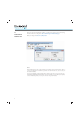
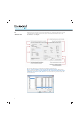
2.2 “Enclosure” Tab Although we don’t use all the options in this Tutorial Project, the following illustration provides a short explanation of all the options in this tab. For more detailed information, refer to the User Manual or the Help file. The enclosure dimensions are required for calculating the temperature rise. Choose “Select from database” and select the [ Select Enclosure ] button. Then pick the fitting enclosure from there.
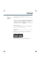
2.2 “Enclosure” Tab In our Tutorial Project, we want to enter the dimensions manually. Configure your enclosure as in the screen shot below: (continued) • Number of enclosures: 1 • Enter the dimensions manually: W = 1,000, H = 1,400, D = 400 mm • Configure the type of installation: rear face covered, all other surfaces free Note: The term “covered” means the enclosure surface is against another structure such as the wall of the building or another enclosure. 2.
2.3.1 Import a Components List Generated with MCS Star Next, select the [ Evaluate ] button. • In the window “Evaluate Dissipation for Enclosure 1” select [ Import MCS Star ] • Enter or select the filename of the DBF file you have exported before from MCS Star • Select the [ Import ] button Note: TRCS does a look-up in the Rockwell Automation Components database. The power-loss data for all components are stored there as follows: • P0 Constant losses (e.g.
2.3.1 Import a Components List Generated with MCS Star (continued) If one or more components are not found in the “Components database”, the particular rows appear highlighted in yellow. This will make the user aware of a need to enter the data manually. Determine the constant losses and the losses proportional to the current and enter them in the corresponding fields below the table (previous picture).
2.3.2 Add Additional Components Now we want to add a 400VA control transformer. This product is not in the Rockwell Automation Components database, so we have to add it as a specific component manually. Note: If it is considered to be a recurring product, it would make sense to save it in the User Component database. For more information about the User Component database see User Manual or Help file. Select [ Specific components ], then select “Add new dataset”.
2.3.2 Add Additional Components Now select again [ Specific components ], then select “Add New Dataset” and add two CC fuses, 3 A. Enter the parameters as shown in the picture below and select the [ OK ] button. (continued) The newly added components appear at the end of the components table. Now enter the quantities and the operating current as shown in the next picture. The transformer is considered to run at constant power loss, so the Operating Current is not required.
2.3.3 Add Power Conductors Now we need to add the power conductors for the supply line and all the loads to the list. Consider an average conductor length of 1.5 m (just the length internal to the panel is to be considered) and select the wire sizes according to the required standard. The size of the supply line is 350 MCM (this information is provided from MCS Star as well). Select the [ Busbars/Conductors ] button and select “Add new dataset”. Select the “Conductor” option under “North America”.
2.3.4 Review the List of Components The number of components and conductors, as well as the operating current (if it does not correspond to the reference current displayed) and a reduction factor, if any, must be entered into this list. The components imported from MCS Star usually don’t need to be changed, except when more accurate information about the Reduction Factor is known.
2.4 “Temperature Rise According to IEC 60890” Tab This tab shows the result of the temperature rise calculation as a temperature profile within the enclosure. If there are multiple enclosures in a row, there will be a numbered button for each one. The active enclosure can be selected using the buttons at the top, without having the need to switch back to the “Enclosure” tab. IEC 60890 refers to cabinets with natural convection. If devices with integral fans are used, this assumption no longer applies.
2.4 “Temperature Rise According to IEC 60890” Tab IEC 60890 Details Selecting the [ IEC 60890 Details ] button will display the calculation parameters in accordance with IEC 60890. (continued) The constants k, c and f are determined according to IEC 60890, they are required for the calculation of the heat dissipation excess. These numeric values don’t have any units of measure.
2.4.1 Measures to Take in Case of Heat Dissipation Excess In our Example, the calculation shows an excess heat dissipation of 60 W, which would cause a temperature excess of 4 °C on top of the enclosure. Let’s try different measures to solve this issue. Make sure you change the settings back to the original values before trying each solution. • Select a bigger enclosure. If you are not limited by space, this is a very efficient method without an influence to the ingress protection level of the enclosure type.
2.5 “Result Cooling + Heater” Tab The temperature rise assessment according IEC 60890 is recognized as a proven method for most standard panels. It refers to cabinets with natural convection only. The “Result Cooling + Heater” tab provides some additional information and functionality.
2.6 Viewing and Printing Reports The results of the temperature rise calculation can be printed. The report includes the bill of materials and all components with their individual power dissipation values. This document is intended to be a part of the project documentation. Select the button [ Print Preview ], menu option “Project”. Note: In a project with only one enclosure, there is no diff erence between “Selected Enclosure” and “Project”. Use the buttons to navigate, zoom and print the document.
Conclusion You have now completed the tutorial project and you have learned the basics of using the Temperature Rise Calculation Software, TRCS. Please consult the Help file and the User Manual for more detailed information and features we have not covered in this tutorial, e.g.
Publication 141A-IN004A-EN-P – July 2010 Copyright © 2010 Rockwell Automation, Inc. All Rights Reserved. Printed in USA.