
Manual


6
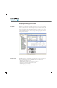
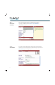
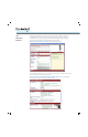
You will now see a graphical representation of the busbar rack. MCS Star adds additional
busbar supports if the rack length exceeds the allowable support spacing. is is based upon
the SCCR requirements and the size of the busbar. You will also notice that a bill of material is
being created on the left hand side of the window for all the components required to assemble
the system.
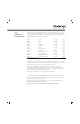
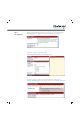
Note: e center support was added because of the mechanical strength of the busbar.
It is based upon the graph below.
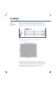
e force between conductors is proportional to the square of the instantaneous current.
In case of a short circuit, which is protected by a short-circuit protective device (SCPD), the
maximum force occurs at the peak let-through current of the protective SCPD (circuit breaker or
fuse). e higher the forces during a short-circuit are, the narrower the spacing between busbar
supports needs to be. Observe that the peak value of the s-c current is plotted on the y-axis.
e maximum support distances for smaller cross-section conductors are given by pure
mechanical considerations, i.e. static loads and plugging forces.
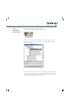
Step 4:
Enter Supply Data
(continued)