MCS™ Star Configuration Software – Tutorial
Table of Contents Page Designing a Mounting System Solution Introduction . . . . . . . . . . . . . . . . . . . . . . . . . . . . . . . . . 2 1. Identify System Loads and Parameters . . . . . . . . . . . . . . . . . 3 2. Enter System Information . . . . . . . . . . . . . . . . . . . . . . . 4 3. Enter Rack Data . . . . . . . . . . . . . . . . . . . . . . . . . . . . 4 4. Enter Supply Data . . . . . . . . . . . . . . . . . . . . . . . . . . . 5 5. Configuring Two Component Starters . . . . . . . . .
Designing a Mounting System Solution Introduction MCS Star is a powerful product selection and system planning software as well as a graphical design tool. It allows the user to configure a multitude of starter and loadfeeder variations and then visually represents the configuration on the graphical interface. The software can help design systems compliant with UL/CSA or IEC standards. It also calculates wire sizing, support spacing and dimensional restrictions.
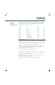
Step 1: Identify System Loads and Parameters Below is the list of motors and loads that will be used in our tutorial. We need to configure a horizontally mounted busbar assembly for a line voltage of 480V 60 Hz, control voltage 120V 60 Hz, designed per UL standards, in a 900 mm wide cabinet and have a short-circuit current rating (SCCR) of 5 kA.
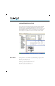
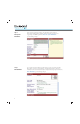
Step 2: Enter System Information In the appearing configurator window, select the busbar system parameters. Here you specify the electrical standards, the units of measure you prefer to use, supply voltage and SCCR requirements. Enter the “System Information” per the following example. Step 3: Enter Rack Data As you scroll down the left hand side of the window, you can now enter the rack data. This is where you enter the rack orientation, the busbar length and size, and support information.
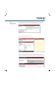
Step 4: Enter Supply Data Finally, you will enter the supply information such as supply type, position and terminal size. Enter “Supply Data” per the following example. Then select the [ Accept ] button. You will now configure the feeder circuit breaker. Enter the “Circuit Breaker Data” per the following example. You will also need lugs on the line side of the circuit breaker for the incoming power. Enter the “Terminal Lug Data” per the following example. Then select the [ Accept ] button.
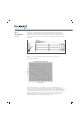
Step 4: Enter Supply Data (continued) You will now see a graphical representation of the busbar rack. MCS Star adds additional busbar supports if the rack length exceeds the allowable support spacing. This is based upon the SCCR requirements and the size of the busbar. You will also notice that a bill of material is being created on the left hand side of the window for all the components required to assemble the system. Note: The center support was added because of the mechanical strength of the busbar.
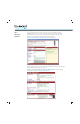
Step 5: Configuring Two Component Starters The next step is to configure two component starters. First, select the [ Product Library ] button in the main tool bar. In the Product Library window, select the desired starter type. Since Motor 1 requires a DOL starter with no special overload requirements, you can select the Bulletin 103S and select the [ OK ] button. You will notice that some parameters may be pre-loaded. The supply voltage is inherited from the busbar rack parameters.
Step 6: Enter Starter Parameters Here you will enter the control voltage, the type of short-circuit coordination required, the SCCR required, horsepower or motor FLA, the starter style and the type of mounting module desired. Let’s choose a Type F starter which will also require the Type E spacing adapter. The starter will be mounted on the MCS Iso busbar module. Enter the “Starter Parameters” for Motor 1 per the following example.
Step 6: Enter Starter Parameters Once you select the [ Accept ] button below the catalog number, the starter drawing will be added to the rack in the graphical interface, as well as the product detail in the bill of material. (continued) You could configure the next starter by repeating the same steps for Motor 2. Since this is a DOL starter, you would choose Bulletin 103S from the Product Library. After entering all the starter parameters for Motor 2, select the [ Accept ] button.
Step 8: Editing Component Attributes You can now edit the parameters of the copied starters to match the loads for Motors 2 and 3.
Step 8: Editing Component Attributes (continued) Configurator selections for Motor 4: • • • • Rated Conditional Short-circuit Current (Iq) = 5 kA Horsepower = 5 Hp Starter Type = 107S Press Accept Once you configure the first reversing starter, you can copy it and adjust the Hp requirements as you did for Motor 2. Configurator selections for Motor 5: • Horsepower = 1.5 Hp • Press Accept Step 9: Configuring a Drive Select the [ Product Library ] icon in the main tool bar as you did in Step 5.
Step 9: Configuring a Drive Enter the “General Starter Data, PowerFlex 4 Data and SCPD Data” for Motor 6 per the following example. Then select the [ Accept ] button. (continued) Since we know the remaining starters will not fit on the existing busbar rack, we will need to add another rack to the assembly. Before we do this, we will need to add a supply module to the first rack in order to distribute power to the second.
Step 9: Configuring a Drive Click on the [ Product Library ] icon. Select “General Purpose Load Feeders” and select the [ OK ] button. (continued) Since we know that the FLA of the remaining loads is 70.4 A, we can enter this in the Load FLA section, then choose the “Supply Module” as the supply type. Enter the “Supply Module” data per the following example. Then select the [ Accept ] button.
Step 10: Moving Components Sometimes you will need to move components around on the busbar rack to make the most efficient use of space. Let’s move the supply module to the far right-hand side of the rack. To move a component, press and hold the left mouse button on the object to be moved. Then, simply drag it to the desired position and let go of the button. You will notice that the program only allows the supply module to be positioned to the left of the main circuit breaker.
Step 10: Moving Components Now let’s tighten up the spacing by moving the middle busbar support to the right, up against the motor starter 3. Notice the other components will move to the right along with it. (continued) Step 11: Adding Additional Racks Now we need to add the second rack. This can be done by clicking on “Mounting System” in the main tool bar and then selecting “Add Rack”.
Step 12: Changing Supply Type The additional rack will be identical to the first one we set up. Since the main circuit breaker was sized for all the loads, we can feed the second rack with a supply module. To change the supply type in the second rack, right mouse click somewhere on the second rack. You will see a drop down menu. Click on “Edit Rack Parameters”. You can then change the supply type to a “supply module”. Enter the “Supply Data” per the following example. Then select the [ Accept ] button.
Step 12: Changing Supply Type (continued) We can now add the rest of the components to the second rack. Step 13: Adding a Circuit Breaker For the Resistive Load 7, we can add the circuit breaker in the same way we added the supply module to the first rack. Click on the [ Product Library ] icon again. Select “140U Molded Case Circuit Breakers” and select the [ OK ] button.
Step 13: Adding a Circuit Breaker (continued) 18 You will now have to configure the circuit breaker. Enter the “140U Molded Case Circuit Breaker” data per the following example. Then select the [ Accept ] button.
Step 14: Configuring a Soft-Starter Now we need to add the SMC-3 to the busbar assembly. Repeat the process you used for Motor 1, except we need to configure a SMC Starter with the following steps. Click on the [ Product Library ] icon. Select “SMC Starter for Direct On-line Connected Motors” and select the [ OK ] button. Enter the “SMC Starter” data for Motor 8 per the following example. Then select the [ Accept ] button.
Step 14: Configuring a Soft-Starter (continued) All that’s left is to add the remaining 4 Three Component Starters. Because more advanced overload protection is required for these motors, we need to select the 103T and 107T, Three Component Starters.
Step 15: Configuring Three Component Starters As before, click on the [ Product Library ] icon and from the window select 103T starters and select the [ OK ] button.
Step 15: Configuring Three Component Starters (continued) 22 Because we need more information about the overload protection, we need to fill in the type of overload required. Let’s fill in all of the parameters and choose the 193-EE. Enter the “103T Starter” data for Motor 9 per the following example. Then select the [ Accept ] button.
Step 15: Configuring Three Component Starters (continued) As before, we can copy the starter and change the parameters for Motor 10. All we have to change is the overload relay type. In this case, we need the 193-EC. Change the “Overload Relay Type” to 193-EC for Motor 10 per the following example. Then select the [ Accept ] button.
Step 15: Configuring Three Component Starters (continued) Let’s create the last two reversing starters by selecting the 107T from the Product Library window. Click on the [ Product Library ] icon and from the window select 107T starters and select the [ OK ] button.
Step 15: Configuring Three Component Starters Enter the “107T Starter” data for Motor 11 per the following example. Then select the [ Accept ] button. (continued) • • • • • Configurator selections for Motor 11: Rated Conditional Short-circuit Current (Iq) = 5 kA Horsepower = 2 Hp Starter Type = 107T Overload Type = 193-ED Press Accept Since Motor 12 is identical to Motor 11, just copy it.
Step 15: Configuring Three Component Starters (continued) Now let’s tighten up the spacing by moving the middle support to the right of the 107Ts. This will move it more towards the center of the rack. Press and hold the left mouse button on the object to be moved. Then, simply drag it to the right side, touching (overlapping) the starter for Motor 11. The program will ask if you want the support to be positioned to the left or right side of the object it is touching, select “Right” side.
Additional MCS Star Configuration Software Functionality Adding Busbar Covers To cover up the exposed busbar, we should add busbar covers to provide finger-safe protection on both racks. Right click on the exposed busbar and select “Create Busbar Cover” from the pop-up window. Let’s go with the individual covers. These come in 1000 mm lengths and can be cut to the required length to cover the exposed busbar. Select the “Individual Busbar Covers” and select the [ Accept ] button.
Adding Busbar Covers (continued) Creating Labels for the Racks or Components 28 If you wish to change the names of your racks, simply right mouse click in the area near the padlock symbol. Click on the “Rename” option and type in the new name.
Creating Labels for the Racks or Components To add labels to the components on the busbar, right click on the component, choose the “Rename” option and type in the new name. (continued) Repeat this step for all the other components.
Locking the Rack Design Now that the rack design is complete, we can lock the configurations by double clicking on the unlocked padlock symbol. If you need to make changes later, you can unlock the rack by double clicking on the locked padlock symbol. You will notice that MCS Star calculates the conductor size requirements.
Exporting Drawings MCS Star provides drawing export capability in the universal DXF format (Drawings EXchange Format). Almost all CAD/CAE programs can import this format. This way, MCS Star drawings can be integrated in complete panel layouts. To export the assembly layout drawing, from the menus at the top of the screen, select “Mounting System” and “Export DXF Drawing”. You will be asked to name the file and where you would like it saved.
Exporting Drawings Once saved, you can open the file with your CAD/CAE software. (continued) Exporting Assembly to TRCS (Temperature Rise Calculation Software) 32 To export your assembly to a file that can be imported into TRCS, click on the File Menu > Export > Temperature Rise Calculation (TRCS) File link. This will bring up a dialog box that allows you to save a DBF file that can be imported into TRCS.
Printing and Exporting Data Depending upon your configuration, several documents are provided for each starter: • Configuration sheet • Wiring diagram (IEC or ANSI) • Layout drawing To view or print the documents of a particular starter, click the “Product Cfg” tab at the bottom of the screen. Then, highlight the desired starter in the “Project Details” window. Once the starter catalog number appears in the upper right window, highlight the required document and select the [ View ] or [ Print ] button.
Printing and Exporting Data If you wish to print multiple documents at once, from the menus at the top of the screen, select “File” and then “Print Multiple”. You can also select the [ Print Multiple ] icon from the toolbar. (continued) Check the desired documents you wish to print and select the [ OK ] button.
Printing and Exporting Data You can also export the project list as a CSV file which can be opened and saved in Excel. Select the [ Export ] icon and click on “Project List”. (continued) You will then be asked what format you would like the file to be saved as. Click on CSV and select the [ OK ] button. Choose the directory and file name, then select the [ Save ] button.
User Defined Devices Let’s say you decide the busbar assembly shall contain a 194E-A160-1753 load break switch, mounted on a busbar adapter. This device is not available in MCS Star, but the program provides a solution called User Defined Devices (UDD). This is a separate part of the software that allows the configuration of non-standard busbar mounted devices and adds them to your Product Library. For more information, see the “User Guide” in the UDD wizard “Help” file.
User Defined Devices It will then be added to the busbar assembly. (continued) Add the bus bar covers, name the UDD and re-lock the rack.
Publication 141A-IN003A-EN-P – July 2010 Copyright © 2010 Rockwell Automation, Inc. All Rights Reserved. Printed in USA.