
Owner manual

6 Differential Air-pressure Transmitter
Publication 1414-IN011B-EN-P - July 2010
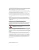
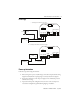
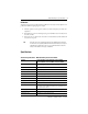
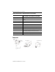
The input pressure range is set by moving two jumpers to the appropriate range. The available
ranges are marked 1…8 on the circuit board. The two jumpers must be set to the same range or
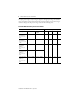
incorrect readings result. The pressure ranges are shown in the following chart:
Available Differential Air-pressure Transmitters
Low Pressure Transducer Jumper selectable pressure range
Description Commercial Industrial,
cc-pcb
123 4
Room differential
w/4-20mA±2.5”,
±5.0”,0-5”,0-10”
WC
1414-CPZ10FVRAA ±2.5 in. ±5.0 in. 0…5 in. 0…10 in.
Room differential
w/4-20mA±5.0”,
±10.0”,0-10”,0-20
” WC
1414-CPZ10FRRAA ±5.0 in. ±10.0 in. 0…10 in. 0…20 in.
Room differential
w/4-20mA &
LCD±2.0”,
±4.0”,0-4”,0-8”
WC
1414-CPD10PNRAA 1414-IPD10FNRAA ±2.0 in. ±4.0 in. 0…4 in. 0…8 in.
Static differential
w/4-20mA & duct
probe±2.0”,
±4.0”,0-4”,0-8”
WC
1414-CPZ10FNDAA 1414-IPZ10FNDAA
Static differential
w/4-20mA & duct
probe±3.0”,
±6.0”,0-6”,0-12”
WC
1414-CPZ10FODAA 1414-IPZ10FODAA ±3.0 in. ±6.0 in. 0…6 in. 0…12 in.