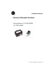
Installation Instructions Electronic to Pneumatic Transducer Catalog Number(s) 1414-INZ10ZXPBP, 1414-CNZ10ZXPBP Publication 1414-IN006A-EN-P - October 2005
Electronic to Pneumatic Transducer Important User Information Solid state equipment has operational characteristics differing from those of electromechanical equipment. Safety Guidelines for the Application, Installation and Maintenance of Solid State Controls (Publication SGI-1.1 available from your local Rockwell Automation sales office or online at http://www.literature.rockwellautomation.com) describes some important differences between solid state equipment and hard-wired electromechanical devices.
Electronic to Pneumatic Transducer 3 Preparation ATTENTION Disconnect the power supply before installation. • Do not exceed the ratings of the device. • Make all connections in accordance with the wiring diagram and electrical codes. • Particles in the air supply larger than 0.03 microns may adversely affect the reliability and life of the transducer. An in-line air filter(1) is recommended for installation between the main air supply and the main air port of the device.
Electronic to Pneumatic Transducer The transducer is jumper selectable. The factory default setting is 2-wire, loop powered 4 to 20 mA device requiring a 4 to 20 mA signal connected to the INPUT and COM terminals. The unit may also be configured for 3-wire, 0 to 10V dc operation by carefully changing the location of the jumper. Three-wire operation requires a 24 to 30V ac or DC supply connected to PWR and COM terminals in addition to the 0 to 10V dc signal applied to the INPUT terminal. 3.
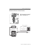
Electronic to Pneumatic Transducer 5 Wire/Connect the Electronic to Pneumatic Transducer PWR – 24 to 30 Vac/dc (0 to 10V dc only) COM – POWER/SIGNAL COMMON INPUT – 0-10Vdc OR 4-20mA Loop power supply Analog Current / Voltage Output PWR only used with 0-10 VDC input selected C OM + INP UT 24 VDC PW R - Electronic to Pneumatic Tranducer ANL VDC+ ANL OUT 0 + ANL COM Publication 1414-IN006A-EN-P - October 2005
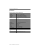
Electronic to Pneumatic Transducer Specifications Electronic to Pneumatic Transducer Specifications Specification Value Input Signal 4…20mA, 0…10V dc jumper selectable Input Impedance 4…20mA input, 400 Ω minimum, 550 Ω maximum Power Supply 4…20mA input, Loop powered; 1.0 Watt maximum Air Supply 138 kPa (20 psig) nominal, 207 kPa (30 psig) maximum Clean, dry, oil-free air required. Air Consumption 5.66 ml/s (0.
Electronic to Pneumatic Transducer 7 Publication 1414-IN006A-EN-P - October 2005
All other trademarks are the property of their respective holders, and are hereby acknowledged. Publication 1414-IN006A-EN-P - October 2005 Supersedes Publication XXXX-X.X.X - Month Year PN 40055-236-01(1) Copyright © 2005 Rockwell Automation, Inc. All rights reserved. Printed in the U.S.A.