
Instruction Manual

Duct Temperature Transmitter 5
Publication 1414-IN005B-EN-P - July 2010
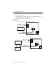
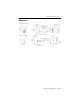
Field Calibration
The unit can be calibrated in the field by using precision resistor values equal to the zero and
span of the transmitter temperature range.
1. Disconnect the sensor from the transmitter and connect the resistor that represents the
zero value to the EXC and NEG terminals.
2. Adjust the ZERO pot until the desired output is achieved.
3. Connect the resistor that represents the span value to the EXC and NEG terminals.
4. Adjust the SPAN pot until the desired output is achieved.
Repeat these steps until no further adjustment is required.
Specifications
TIP
If the unit uses a three-wire sensor, a jumper must be placed between EXC and
SEN.
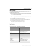
Technical Specifications - Duct Temperature Transmitter
Attribute 1414-CTQx, 1414-CTPx, 1414-ITQx, 1414-ITPx
Operating temperature range -20…105 °C (-4…221 °F)
PCB operating temperature range 0…70 °C (32…158 °F)
Sensor types PT1000 Ω Platinum RTD
Commercial and Hybrid: ±0.3% Class B
Industrial: ±0.2% Class A
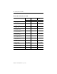
Enclosures Plastic ABS - UL94-V - NEMA 1
Aluminum - NEMA 3R
Cable type PVC insulated, parallel bonded
Probe 304 stainless steel with spin welded tip
Output signal 4… 20 mA current loop
Transmitter accuracy ±0.1% of span, including linearity
Power supply 15…35V DC
Consumption Current: 22.5 mA Max. (with open sensor)
Wiring connections Screw terminal block (14…22 AWG)