
Manual

4 Air Flow Switch
Publication 1414-IN003A-EN-P - October 2005
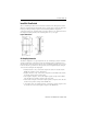
Figure 2 Alarm or Control
Field Adjustment
From lowest operating point several turns of the adjusting screw are necessary to
engage the calibration spring. No change in set point will occur until the spring is
engaged. For higher set points continue turning screw in a clockwise direction. It
may be useful to connect a manometer in parallel with the switch when adjusting,
as the final operating point can be noted for future reference. Please see
specifications for actual ranges and set point information.
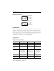
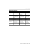
Specifications
Air Flow Switch Specifications
Specification 1414-CPN10APWAB 1414-CPN10APQAB 1414-CPM10APWAB
Sample Media Air Air Air
Mounting Position Diaphragm in any vertical
plane
Diaphragm in any
vertical plane
Diaphragm in any
vertical plane
Field Adjustable
Range
.05, ±.02” w.c. to 12” w.c. .05, ±.02” w.c. to 2” w.c. .40, ±.06” w.c. to 12” w.c
Switch Differential Progressive, increasing
from approximately .02±
.01” w.c. at minimum set
point, to approximately .8”
w.c. at maximum set point.
Progressive, increasing
from 0.02± 0.01” w.c. at
minimum set point to
approximately 0.1” w.c.
at maximum set point.
Progressive, increasing
from approximately .06±
.01” w.c. at minimum set
point, to approximately
.8”w.c. at maximum set
point.
Maximum Pressure .5” (0.03 bar) .5” (0.03 bar) .5” (0.03 bar)
Operating
Temperature Range
-40°C … 82.2°C
(-40°F…180°F)
-40°C … 82.2°C
(-40°F…180°F)
-40°C … 82.2°C
(-40°F…180°F)
C
C
NO
NC
NC
NO
Alarm
Cont ro l
Cont ro l
Alarm
To prove excessive airflow or pressure
To prove insufficient airflow or pressure