
Manual


7 Publication 1413-UM001C-EN-P - May 2006
Chapter
2
Installation
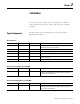
The capacitor bank controller system is supplied as a number of
components that you assemble, install, and connect in a suitable
enclosure.
System Components
The key number in the component lists are referenced in the
illustrations that follow.
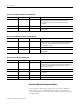
All Configurations
Key Quantity Part Number Description
1 1 1764-24BWA MicroLogix 1500 base unit with: 120/240V ac control power,
(12) 24V dc inputs, and (12) relay outputs
2 1 1764-LRP MicroLogix 1500 enhanced processor
3 1 1764-DAT MicroLogix 1500 data access tool
4 1 1761-NET-AIC Advanced interface converter (used for PM comms)
5 1 1761-CBL-AC00 MicroLogix controller to AIC+ cable, 9-pin D-shell to 9-pin D-shell,
45
cm (17.1 in.) long
6 1 1404-DM Powermonitor 3000 display unit with 3 m (9.84 ft) cable
Base Unit with Serial Meter 1413-CAP-MSA
Key Quantity Part Number Description
7 1 1413-M5000 A Powermonitor 3000-M5 meter with RS-485 communications port
including programmed MicroLogix 1500 8 k memory module with
real-time clock (1764-MM1RTC)
Base Unit with Ethernet Meter 1413-CAP-MEA
Key Quantity Part Number Description
7 1 1413-M5ENT A Powermonitor 3000-M5 meter with Ethernet communications port
including programmed MicroLogix 1500 8 k memory module with
real-time clock (1764-MM1RTC)