
Manual

Publication 1413-UM001C-EN-P - May 2006
30 Installation
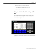
N7:43 Control
Word
(1)
This is the control word for the capacitor bank
controller. The first three (3) bits of the control
word is used to set the CTPT Mode. Bit 4 is used
to initiate a restore of factory defaults. This
should be treated as a momentary state. Bit 5 is
used to initiate the step size buffer. This bit should
also be treated as a momentary state. Bit 6 is
used for disabling step tolerance. The BCD value
for each bit is available for easy setup.
Examples
- CTPT Mode 2 and Disable Step Tolerance = 68
- CTPT Mode 0 and Restore Factory Defaults = 17
to initiate a restore, then 1.
- CTPT Mode 1 and Initiate Step Buffer = 34 to
initiate step buffer, then 2
43 Ext
Configuration
2
N7:44 Unbalance
Alarm Time
seco
nds
The amount of time before alarming and resetting
the Unbalance Alarm flag
44 Ext
Configuration
1
N7:45 Number of
Powermonit
or meters
The number of Powermonitor meters to include in
the aggregate kW and kVAR calculations
45 Configuration
N7:46 Number of
Capacitor
Steps
The number of capacitor steps to be controlled 46 Configuration
N7:47 Operating
Mode
The operating mode:
0 - Manual
1 - Linear
2 - Balanced
3 - Best Fit
4 - User Defined
5 - % Voltage THD
47 Configuration
N7:59 Number of
Samples
The number of kVAR samples to average together
when auto-configuring capacitor step sizes.
1 - 10 5 - Ext
Configuration
1
(1)
Please see the Control Word table.
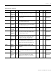
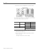
Control and Status Parameters
Address Parameter Unit Description Range Default DAT
INT
PanelView
Screen
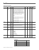
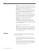
Control Word
Bit Parameter BCD Value
0 CTPT Mode 0 - Normal 1
1 CTPT Mode 1 - Neutral 2
2 CTPT Mode 2 - Retro 4
3 8