Capacitor Bank Controller 1413-CAP User Manual
Important User Information Solid state equipment has operational characteristics differing from those of electromechanical equipment. Safety Guidelines for the Application, Installation and Maintenance of Solid State Controls (publication SGI-1.1 available from your local Rockwell Automation sales office or online at http://literature.rockwellautomation.com) describes some important differences between solid state equipment and hard-wired electromechanical devices.
Table of Contents Preface Who Should Use This Manual . . . . . . . . . . . . . . . . . . . . . . . . 3 Additional Resources. . . . . . . . . . . . . . . . . . . . . . . . . . . . . . . 3 Chapter 1 General Information Introduction . . . . . . . . . . . . . . . . . . . . . . . . . Description of the Capacitor Bank Controller . Functions . . . . . . . . . . . . . . . . . . . . . . . . Options . . . . . . . . . . . . . . . . . . . . . . . . . . . . . . . . . . . . . . . . . . . . . . . . . . . . . .
2 Table of Contents Chapter 4 SCADA Interface Power-circuit Parameters . . . . . . . . . . . . . . . . . . . . . . . . . . . 49 Chapter 5 Add Special Functionality PFMGR4 Logic . . . . . . . Overview . . . . . . . . Power Factor Alarm . Step Control . . . . . . Step Routine . . . . . . User Variables . . . . . . . . . . . . . . . . . . . . . . . . . . . . . . . . . . . . . . . . . . . . . . . . . . . . . . . . . . . . . . . . . . . . . . . . . . . . . . . . . . . . . . . . . . . . . . .
Preface Read this to familiarize yourself with the rest of the manual. It provides information concerning: • who should use this manual. • where to go for more information. Who Should Use This Manual Use this manual if you are responsible for designing, installing, programming, or troubleshooting the Capacitor Bank Controller system. You should have a basic understanding of electrical circuitry and familiarity with relay logic. If you do not, obtain the proper training before using this product.
4 Preface Publication 1413-UM001C-EN-P - May 2006
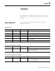
Chapter 1 General Information Introduction The capacitor bank controller is a replacement for standard, fixed-function capacitor controllers currently on the market. The controller consists of standard, off-the-shelf, Allen-Bradley hardware with the application ladder code necessary to perform power factor correction. The controller is designed to provide the same base functionality as a fixed-function capacitor bank controller.
6 General Information • Alarms – Bad step, indicates blown fuse, capacitor failure – Target power factor not achieved – High / Low voltage – %THD High – Current unbalance – Metering • Powermonitor data concentrated into the MicroLogix 1500 controller • Phase current, line voltage, frequency, real and reactive power, power factor and THD Options • Up to three additional Powermonitor meters to aggregate up to four total feeds • PanelView 550 keypad HMI terminal with serial or Ethernet communications • Ethe
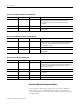
Chapter 2 Installation The capacitor bank controller system is supplied as a number of components that you assemble, install, and connect in a suitable enclosure. System Components The key number in the component lists are referenced in the illustrations that follow.
8 Installation Optional Serial HMI, Serial Meter 1413-CAP-MS-PSA Key Quantity Part Number Description 7 1 1413-M5000NM A Powermonitor 3000-M5 meter with RS-485 communications port including programmed memory module with real-time clock (1764-MM1RTC) and programmed 2 MB flash memory card (2711-NM13) 8 1 2711-NC21 PanelView terminal to MicroLogix communication cable 9 1 2711-K5A16 PanelView 550 operator terminal with RS-232 DF1 serial communications Optional Serial HMI, Ethernet Meter 1413-C
Installation System Architecture 9 This section illustrates the base system with the serial and Ethernet options. Base System with Serial Options 2 4 9 3 PanelView 550 Allen-Bradley 7 8 9 4 5 6 1 2 3 . 0 <-F1 F2 F3 F4 F5 F6 F7 F8 F9 F10 - <-------' ^ < > v 8 5 Optional Serial HMI 1 6 Allen-Bradley Powermonitor 3000 25.04M WATT L1 Allen-Bradley Powermonitor 3000 25.04M WATT L1 Allen-Bradley Powermonitor 3000 25.04M WATT L1 Allen-Bradley Powermonitor 3000 25.
10 Installation Base System with Ethernet Options 2 4 11 3 13 10 PanelView 550 Allen-Bradley 7 8 9 4 5 6 1 2 . 0 <-F1 F2 F3 F4 F5 F7 F8 F9 - ^ < F6 3 <-------' > F10 v 5 12 1 Optional Ethernet HMI Ethernet Local Area Network by Customer 6 Allen-Bradley Powermonitor 3000 25.04M WATT L1 Allen-Bradley Powermonitor 3000 25.04M WATT L1 Allen-Bradley Powermonitor 3000 25.04M WATT L1 Allen-Bradley Powermonitor 3000 25.
Installation Assemble, Mount, and Connect Your Controller 11 This section describes how to mount the MicroLogix 1500 controller and connect it to an AIC+ interface and PanelView module for use with the capacitor bank controller. MicroLogix 1500 Controller (All Configurations) TIP Please refer to Publication 1746-UM001, Chapter 2, for information on performing these tasks. 1. Mount the MicroLogix 1500 base unit (1). Mounting Template 2. Install the MicroLogix 1500 processor module (2).
12 Installation 3. Install the MicroLogix memory module (7a). This module may be found packaged with the Powermonitor meter (7). 4. Install the data access terminal (3). 5. Connect the MicroLogix 1500 controller to 120V ac control power, earth ground, capacitor step contactors (or interposing relays as required), and an alarm circuit as shown in the wiring diagram. Wire the Controller Fault-protection relays can be used to immediately discharge all or specific capacitor steps during a fault occurrence.
Installation 13 Output 0 is used as an alarm relay and is wired normally open to an external alarm indicator. Output 1…10 is wired to normally-open contactors for each respective capacitor step.
14 Installation AIC + Interface Converter (All Configurations) 1. Mount the AIC+ communications converter (4) within 45 cm (18 in.) of the left edge of the MicroLogix 1500 controller. 5 1 4 2. Connect the DB9 to DB9 cable (5) between Port 1 of the AIC+ (4) and Channel 1 of the MicroLogix 1500 controller (1). 3. Connect a source of 24V dc to the control power terminals on the bottom of the AIC+. The 24V dc power may be obtained from the DC Power Out terminals on the MicroLogix 1500 controller. 4.
Installation AIC+ Blue Blue CLR CLR SHLD SHLD 15 Powermonitor 3000 Device SHLD RS-485 _ + 24 V Power Supply Red Black AIC+ Powermonitor 3000 Meter A - B + SHLD SHLD 3. Connect any additional, optional Powermonitor meters RS-485 ports in a daisy-chain fashion, + to +, - to -, Shld to Shld. In certain cases, terminating resistors may improve communications robustness. Refer to publication 1404-IN007 for more information. 4.
16 Installation PanelView 550 Serial Terminal (Serial HMI options) 1. Mount the PanelView 550 HMI terminal in a suitable cutout within 5 m (16 ft) of the MicroLogix controller. Refer to publication 2711-IN009 for detailed installation instructions. Mounting Studs (3 Top / 3 Bottom) Protective Installation Label Self-locking Nuts (6 used, 8 provided) 2. Install the memory card and retainer.
Installation 17 3. Connect 120V ac control power and earth ground. Power Terminal Block (fixed) 120/240V ac, 3 Wire, U.S. Color Code L1 Black (Line) White (Neutral) L2 GND Green Green (Earth Ground) (Earth Ground) 120/240V ac, 3 Wire, European Harmonized Color Code L1 L2 GND Brown (Line) Blue (Neutral) To Power Source Green/Yellow (Protective Earth) To Power Source 4. Connect the communications cable between the MicroLogix 1500 controller Channel 0 and the PanelView 550 terminal serial port.
18 Installation PanelView 550 Ethernet Terminal (Ethernet HMI Option) 1. Mount the PanelView 550 HMI terminal in a suitable cutout within 100 m (328 ft) of the MicroLogix controller. Refer to publication 2711-IN009 for detailed installation instructions. Mounting Studs (3 Top / 3 Bottom) Protective Installation Label Self-locking Nuts (6 used, 8 provided) 2. Install the memory card (7b, packed with the Powermonitor meter) and retainer.
Installation 19 3. Connect 120V ac control power and earth ground. Power Terminal Block (fixed) 120/240V ac, 3 Wire, U.S. Color Code L1 Black (Line) White (Neutral) L2 GND Green Green (Earth Ground) (Earth Ground) 120/240V ac, 3 Wire, European Harmonized Color Code L1 L2 GND Brown (Line) Blue (Neutral) To Power Source Green/Yellow (Protective Earth) To Power Source 4. Install the Ethernet interface module (9) within 45 cm (18 in.
20 Installation Configuration The capacitor bank controller base unit has been set up to require minimal out-of-box configuration. The base system has default communications settings. Certain circumstances and options require additional configuration of communications, which may include the use of programming software not included with the controller. You are required to configure the Powermonitor meters to coordinate them to the power circuit in the base unit and all options.
Installation 21 Communications Settings Device / Parameter MicroLogix 1500 Controller Chan 0(1) MicroLogix 1500 Controller Chan 1 Powermonitor Meter 1 Protocol DF1 Full Duplex DF1 Half-duplex Master DF1 Half-duplex Slave(1) Baud 19,200 19,200(1) 19,200(1) Source ID / Node Address 1 0 101 Parity / Stop Bits None / 1 None / 1(1) None / 1(1) Handshaking None None(1) None(1) Error Checking CRC CRC(1) CRC(1) (1) Default or out-of-box settings.
22 Installation PanelView 550 Ethernet Configuration Settings Device / Parameter MicroLogix 1500 Controller via NET-ENI PanelView 550 Operator Terminal Powermonitor Meter 1 IP Address 192.168.0.100 192.168.0.105 192.168.0.101 Subnet Mask 255.255.255.0 255.255.255.0 255.255.255.0 Default Gateway 192.168.0.1 192.168.0.1 192.168.0.1 To change from the default Ethernet addresses, additional software is required.
Installation 23 Powermonitor Ethernet Communication Settings Device / Parameter Powermonitor Meter 2 Powermonitor Meter 3 Powermonitor Meter 4 Node Address 102 103 104 IP Address(1) 192.168.0.UnitID 192.168.0.UnitID 192.168.0.UnitID Subnet Mask 255.255.255.0 255.255.255.0 255.255.255.0 Default Gateway 192.168.0.1 192.168.0.1 192.168.0.1 (1) The Unit ID is listed on the Powermonitor nameplate.
24 Installation Parameter Descriptions • Wiring mode – selected to match the physical connections to the power system – Delta 3 CT – Delta 2 CT – Direct delta 3 CT – Direct delta 2 CT – Open delta 3 CT – Open delta 2 CT – Wye (default) – Single phase • PT (VT) primary voltage – reflects the voltage rating on the high side of the potential/voltage transformers. Range 1…10,000,000 V, default 480 • PT (VT) secondary voltage – reflects the voltage rating on the low side of the potential/voltage transformers.
Installation 25 Display Module Key Function POWERMONITOR 3000 L1 L2 L3 N Escape Key Up Arrow Key Down Arrow Key Enter Key Display mode Returns to parent menu Steps back to the previous parameter/menu in the list Steps forward to the next parameter/menu in the list Steps into a sub-menu or sets as default screen Program mode Returns to parent menu Steps back to the previous parameter/menu in the list Steps forward to the next parameter/menu in the list Steps into a sub-menu, selects the para
26 Installation Menu Flowchart Level 1 Display Program Password? Basic 1 Not Used For Cap Bank Controller Setup Advanced Level 2 2 Native Comm. 3 Optional Comm. ... Level 3 Wiring Mode Protocol PT Primary Delay PT Secondary Baud CT Primary Address CT Secondary ... IP Address Subnet mask Default Gateway I4 Primary I4 Secondary ... Controller Configuration Publication 1413-UM001C-EN-P - May 2006 Notes: 1. Base Unit And All Options 2. Additional Power Monitor Options 3.
Installation 27 Control and Status Parameters Address Parameter Unit N7:0 Capacitor Step 1 Measured Size N7:1 Description Range Default DAT INT PanelView Screen kVAR Measured and averaged capacitor size for each step - 0 Configuration Capacitor Step 2 Measured Size kVAR - 1 Configuration N7:2 Capacitor Step 3 Measured Size kVAR - 2 Configuration N7:3 Capacitor Step 4 Measured Size kVAR - 3 Configuration N7:4 Capacitor Step 5 Measured Size kVAR - 4 Configuration N7:5 C
28 Installation Control and Status Parameters Address Parameter Unit N7:10 Capacitor Step 1 Effective Size N7:11 Default DAT INT PanelView Screen kVAR Nameplate capacitor size for each step 50 10 Configuration Capacitor Step 2 Effective Size kVAR 50 11 Configuration N7:12 Capacitor Step 3 Effective Size kVAR 50 12 Configuration N7:13 Capacitor Step 4 Effective Size kVAR 50 13 Configuration N7:14 Capacitor Step 5 Effective Size kVAR 50 14 Configuration N7:15 Capacitor St
Installation 29 Control and Status Parameters Address Parameter Unit Description Range Default DAT INT PanelView Screen N7:32 Voltage Threshold High & Low % The voltage percentage from nominal, that will determine high and low limits for alarming 1 - 10 5 32 Ext Configuration 1 N7:33 %THD Voltage Setpoint % The %THD at which the controller acts to reduce voltage % THD 0 - 100 3 33 Ext Configuration 1 N7:34 Lead Deadband kVAR The leading kVAR limit allowed for the system, before th
30 Installation Control and Status Parameters Address Parameter N7:43 Control Word(1) Unit Description Range Default DAT INT This is the control word for the capacitor bank controller. The first three (3) bits of the control word is used to set the CTPT Mode. Bit 4 is used to initiate a restore of factory defaults. This should be treated as a momentary state. Bit 5 is used to initiate the step size buffer. This bit should also be treated as a momentary state.
Installation 31 Control Word Bit Parameter BCD Value 4 Restore Factory Defaults 16 5 Initialize Step Buffer 32 6 Disable Step Tolerance; 0 = False, 1 = True 64 7 Enable Input Mode; 0 = False, 1 = True 128 Use the DAT for Configuration The data access terminal (DAT) provides a basic configuration interface for the capacitor bank controller. In Integer mode, the DAT provides read/write access to the configuration parameters listed in the Control and Status Parameters table.
32 Installation The auto-configure process begins. During this process, the controller energizes each capacitor-bank step for a short time, measures the steps kVARs and records the value. This process repeats several times and the results of each trial are averaged. When the process is complete, the averaged values are copied to the Effinal_StepSize_Sn parameters and the Auto_Detect_Cap_Size flag is reset.
Installation 33 5. Press the Enter key to store the new value. Esc or INT/Bit keys will discard the new value. 6. Repeat steps 2…5 as needed. Configuration with the PanelView 550 Terminal (Optional HMI Only) The optional PanelView 550 terminal provides you with a more user-friendly interface to the capacitor bank controller. Use the function keys to navigate through the screens and enter data as needed using the keypad. A-B PanelView 550 Allen-Bradley 7 8 9 4 5 6 1 2 3 .
34 Installation 2. Press F10 to view the Configuration screen from the Menu. The controller tags available on the Configuration screen are shown below in their relative location on the screen. Num_Steps Num_PMs kVAR_Lead_DB Mode StepsActive DischgTimerPreset kVAR_Lag_DB Eff_StepSize_S1 Eff_StepSize_S6 Eff_StepSize_S2 Eff_StepSize_S7 Eff_StepSize_S3 Eff_StepSize_S8 Eff_StepSize_S4 Eff_StepSize_S9 Eff_StepSize_S5 Eff_StepSize_S10 Auto_Detect_Cap_Size Initialize_Step_Buffer 3.
Installation 35 5. Press F6 to navigate to the Auto Configure Effective kVAR process. TIP The number of measurements to average for each step is entered on the Extended Configuration Screen #2 (F10). 6. Press F6 to initiate the auto-configuration process. 7. When done, press F10 to return to the Configuration screen. 8. Select the desired operating mode by entering the number or by selecting the description in the list box. The new value is displayed in both formats. 9.
36 Installation F10 navigates to the first Extended Configuration screen. This screen operates in the same way as the initial configuration screen. The controller tags available on the Configuration screen are shown below in their relative location on the screen.
Chapter 3 Operation Introduction The capacitor bank controller gathers real- and reactive-power data using one or more Powermonitor meters. The processor manipulates data in engineering units of kVAR and kW. The unit does not directly control power factor, but rather works to actively minimize imported and exported kVAR. The net result of this philosophy indirectly controls power factor and minimizes voltage excursions associated with excessive kVAR export.
38 Operation • Linear (mode = 1) – This mode of operation switches the capacitor steps on and off in first-in, last-out (FILO) order. That is, the first step on is the last step turned off. This is most useful when all the capacitor steps are of similar sized. • Balanced (mode = 2) – This mode counts the number of opening operations on each capacitor step and switch-capacitor steps to balance the number of opening operations equally across all of the employed capacitor steps.
Operation 39 • 2 = Retro mode - One CT wired on the A phase and one PT wired from phases B to C are installed on a three-phase circuit. The power monitors must be set up in Wye-wiring mode. The controller swaps the values of the real- and reactive-power data produced by the power monitors and multiplies them by 3 . This mode is particularly useful in retrofit applications. Alarms Operator Interface • Bad Step - This alarm indicates a blown fuse and/or loss of capacitor condition.
40 Operation • Ethernet PanelView 550 – A similar HMI to the serial PanelView but using Ethernet communications, offered with the Ethernet HMI option only. Data Access Terminal (DAT) The data access terminal (DAT) provides access to 48 integer and 48 binary data registers. The Binary (bit) Elements and Integer (Word) Elements tables define how these register assignments are made. See Control and Status Parameters on page 27 for the Integer (Word) Elements.
Operation 41 Binary (bit) Elements Address Parameter Value DAT BIT PanelView Screen B3:20 Capacitor Step 1 - Mode 0 = Manual, 1 = Auto 20 B3:21 Capacitor Step 2 - Mode 21 B3:22 Capacitor Step 3 - Mode 22 B3:23 Capacitor Step 4 - Mode 23 B3:24 Capacitor Step 5 - Mode B3:25 Capacitor Step 6 - Mode 25 B3:26 Capacitor Step 7 - Mode 26 B3:27 Capacitor Step 8 - Mode 27 B3:28 Capacitor Step 9 - Mode 28 B3:29 Capacitor Step 10 - Mode 29 B3:30 Capacitor Step 1 - Manual Command B
42 Operation Use the DAT PROTECTED 01 OFF - 0 F1 F2 ESC BIT INT ENTER The data access terminal (DAT) enters the Bit mode automatically after you apply power. Bit mode can also be selected by pressing the BIT key. If Bit mode was already active, the DAT displays the last bit element monitored. If Integer mode was active, the DAT displays the first bit element, after a brief delay during which a working message appears. Press the INT key to select Integer mode.
Operation • • • • • • • • 43 Navigation / Menu Bank Status Extended Status Step Control Power Factor Summary Powermonitoring Data x4 Alarm Summary System Configuration Numeric Keypad Enter Key Function Keys Navigation Keys Screen Navigation Tree Overview Summary F1 Navigation/ Menu F2 Step Status F3 Power Factor Summary F4 PM3K #1 Data F5 Extended Status F3 PM3K #2 Data F5 Step Control F3 PM3K #3 Data F5 Alarm Summary F9 Configuration F10 Extended Configuration F10 Extended Configuratio
44 Operation Overview Summary Screen This is the home screen and displays after you apply power. Press the F1 function key to navigate to the Menu screen.
Operation 45 The status for the steps is listed in vertical columns from 1…10. There are no configurations on this screen. It displays status data only. Mode: A = Automatic, which means the step is controlled based on the operation mode selected. M = Manual, which means you can force the step on or off via the keypad. Step Status: 1 = On, 0 = Off. Discharge Status: ‘-’ = Not Discharging, D = Discharging. Alarm: ‘-’ = No Alarm, ‘*’ = In Alarm.
46 Operation Step Control Screen The steps are listed in vertical columns from 1…10. The first row within the AUTO row commands whether to allow manual or automatic control of each individual step. Use the arrow keys to navigate to each individual command. The second row within the AUTO row, gives the status of each individual step. A = Automatic, M = Manual. The first row within the MANL row commands the step to be turned on. 0 = Off, 1 = On.
Operation 47 Alarm Summary Screen Alarms are listed in the center of the screen. Alarms can be cleared and acknowledged by moving the curser over the appropriate field and pressing the Enter key. Use the up / down keys to change the state and the Enter key to record or save the change. Press the Backspace key to cancel the change. Press the F1 function key to return to the Overview Summary Screen.
48 Operation Powermonitor Meter Screen There are four instances of this screen, one for each of the Powermonitor meters. There are no user-configurable fields on this screen. Press the F5 function key to cycle to the next Powermonitor Data Screen. Press the F1 function key to return to the Overview Summary Screen.
Chapter 4 SCADA Interface Power-circuit Parameters The capacitor bank controller reads power-circuit parameters from the Powermonitor meters and makes that data available in its data table for use by other applications such as SCADA or HMI systems. The following table lists the Powermonitor meter data available in the controller. The symbol x indicates the Powermonitor meter number. Addresses related to Powermonitor meter no. 1 begin with F11:0, addresses related to Powermonitor meter no.
50 SCADA Interface In these systems, all Powermonitor meter data may be accessed using the Ethernet communications port integral to the Powermonitor meter. Please refer to the Powermonitor 3000 User Manual, publication 1404-UM001, for further information.
Chapter 5 Add Special Functionality For added functionality, custom ladder-logic programming and hardware integration are permitted, however, strict guidelines must be followed to comply with warranty contracts. • Altering of existing ladder-logic code is prohibited and will void all warranty contracts. • Additional functionality can only be implemented by adding additional ladder logic code to subroutine PFMGR4. • Additional subroutines may be written, but must be called through PFMGR4.
52 Add Special Functionality Power Factor Alarm The ladder logic code for this section has already been written. The following is an explanation of the ladder logic code for lines one through four. If BUS_NET_KVAR (F8:2) falls outside of the limits defined by KVAR_Lag_DB (N7:35) and PFMGR4_LEAD_DB_NEG (N94:0), then the timer PF_INRANGE__TIMER_4 (T93:0) will be started. The default time for this timer is 60 seconds.
Add Special Functionality 53 Part 1 Example Part 2 If KVAR_LAG_WAIT_2_ADD (B56:0/8) is high and TOTALSTEP_AVAL_AUTO (N70:31) is greater than 0, then output energize KVAR_LAG_ADD_STEP (B56:0/4) and unlatch KVAR_LAG_WAIT_2_ADD (B56:0/8). This will actuate the required step defined by the step routine. See Part 2 Example.
54 Add Special Functionality Part 2 Example Part 3 If KVAR_LEAD_WAIT_2_TRIP (B56:0/7) is high and STEPS_REQUIRED (N7:58) is greater than 0, then Output Energize KVAR_LAG_TRIP_STEP (B56:0/3) and unlatch KVAR_LAG_WAIT_2_ADD (B56:0/7). This will trip the required step defined by the step routine. See Part 3 Example. Part 3 Example Step Routine This section defines what step to use or trip. The outputs for the Step Routine are USE_STEP_NUM (N58:1) and TRIP_STEP_NUM (N58:0).
Add Special Functionality 55 User Variables This chart displays a list of data points and their access rights for use in your custom code. User-defined Variables Symbol Datapoint Description Datatype Units Access Privilege PF_leading B3/.102 This flag indicates the power factor is leading. Bit Read PF_lagging B3/.103 This flag indicates the power factor is lagging. Bit Read Bus_Net_PF F8:00 This register holds the total power factor on the monitored bus.
56 Add Special Functionality User-defined Variables Symbol Datapoint Description Datatype Units Access Privilege Open_8 B3/07 This flag indicates that Contactor #8 has been activated. (0 = Open, 1 = Active) Bit Read Open_9 B3/08 This flag indicates that Contactor #9 has been activated. (0 = Open, 1 = Active) Bit Read Open_10 B3/09 This flag indicates that Contactor #10 has been activated.
Add Special Functionality 57 User-defined Variables Symbol Datapoint Description PM_1_L23 F11:4 PM_1_L31 Datatype Units Access Privilege PM #1, L2-L3 Voltage V Read F11:5 PM #1, L3-L1 Voltage V Read PM_1_Freq F11:6 PM #1, Frequency Hz Read PM_1_P1 F11:7 PM #1, L1 Real Power W Read PM_1_P2 F11:8 PM #1, L2 Real Power W Read PM_1_P3 F11:9 PM #1, L3 Real Power W Read PM_1_PT F11:10 PM #1, Total Real Power W Read PM_1_Q1 F11:11 PM #1, L1 Reactive Power VAR Read PM_
58 Add Special Functionality User-defined Variables Symbol Datapoint Description Datatype Units Access Privilege PM_2_PFT F12:18 PM #2, Total Power Factor PM_2_%THD F12:19 PM #2, measured Total Harmonic Distortion percentage % Read PM_3_I1 F13:0 PM #3, L1 Current A Read PM_3_I2 F13:1 PM #3, L2 Current A Read PM_3_I3 F13:2 PM #3, L3 Current A Read PM_3_L12 F13:3 PM #3, L1-L2 Voltage V Read PM_3_L23 F13:4 PM #3, L2-L3 Voltage V Read PM_3_L31 F13:5 PM #3, L3-L1 Voltag
Add Special Functionality 59 User-defined Variables Symbol Datapoint Description PM_4_Q1 F14:11 PM_4_Q2 Datatype Units Access Privilege PM #4, L1 Reactive Power VAR Read F14:12 PM #4, L2 Reactive Power VAR Read PM_4_Q3 F14:13 PM #4, L3 Reactive Power VAR Read PM_4_QT F14:14 PM #4, Total Reactive Power VAR Read PM_4_PF1 F14:15 PM #4, L1 Power Factor Read PM_4_PF2 F14:16 PM #4, L2 Power Factor Read PM_4_PF3 F14:17 PM #4, L3 Power Factor Read PM_4_PFT F14:18 PM #4, Tot
60 Add Special Functionality Publication 1413-UM001C-EN-P - May 2006
Appendix A Catalog Number Explanation 1413 - CAP - MS - PS A Bulletin Number Series 1413 - Power and Energy Controllers Type of Device CAP - Capacitor Bank Controller MS - Base controller with standard HMI, communicating with one Powermonitor 3000 M5 via RS-485 serial. ME - Base controller with standard HMI, communicating with one Ethernet Powermonitor 3000 M5 via RS-485 serial.
62 Catalog Number Explanation With Ethernet Powermonitor 1413-CAP-ME A Includes base controller and one Powermonitor PM3000-M5 meter on the Ethernet network. Note that ME = Ethernet meter communications. Communications between the MicroLogix controller and the Powermonitor meter are RS-485 serial. Additional HMI To add a serial PanelView 550 HMI to the system, add PS or PE to the catalog number. A PS indicates HMI with serial communications. A PE indicates HMI with Ethernet communications.
Catalog Number Explanation 63 Summary Catalog Number Powermonitor Meters PanelView Terminals MicroLogix Controller to PM Communications MicroLogix Controller to PanelView Terminal Communications MicroLogix Controller to SCADA Communications 1413-CAP-ME A Enet None Serial None Serial 1413-CAP-ME-PE A Enet Enet Serial Enet Enet 1413-CAP-ME-PS A Enet Serial Serial Serial None 1413-CAP-MS A Serial None Serial None Serial 1413-CAP-MS-PS A Serial Serial Serial Serial None Pub
64 Catalog Number Explanation Publication 1413-UM001C-EN-P - May 2006
Glossary Bank An overall capacitor or tuned-filter assembly. This controller is designed to manage and control one bank consisting of 10 steps. Instance An instance of an object represents a complete iteration of an object and all of its attributes and methods. For example, the vacuum switch describes a typical vacuum switch. Each physical switch would result in one instance of a vacuum switch object. Each instance of an object must be managed independently in the software. PM See Powermonitor meter.
66 Glossary Publication 1413-UM001C-EN-P - May 2006
Index A AIC+ 14 alarm summary screen 47 alarms 39 assemble controller 11 MicroLogix 1500 11 B bank status screen 44 C catalog number explanation 61 communications configuration 20 additional Powermonitors option 22 base unit 20 Ethernet HMI option 21 serial HMI option 21 configuration 20 connect controller 11 AIC+ 14 MicroLogix 1500 11 PanelView 550 Ethernet 18 PanelView 550 serial 16 Powermonitor 14 controller configuration 26 PanelView 550 HMI 42 use DAT 31 with PanelView 550 33 D AIC+ 14 MicroLogix 1
68 Index Publication 1413-UM001C-EN-P - May 2006
Rockwell Automation Support Rockwell Automation provides technical information on the Web to assist you in using its products. At http://support.rockwellautomation.com, you can find technical manuals, a knowledge base of FAQs, technical and application notes, sample code and links to software service packs, and a MySupport feature that you can customize to make the best use of these tools.