
Owner's manual


Rockwell Automation Publication 1413-UM001D-EN-P - November 2010 9
Chapter
2
Installation
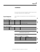
The capacitor bank controller system is supplied as a number of components that
you assemble, install, and connect in a suitable enclosure.
System Components
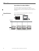
The key number in the component lists are referenced in the illustrations that
follow.
Table 1 - Base Configurations
Key Quantity Cat. No. Description
1 1 1408-EM3-ENT-A PowerMonitor 1000 unit
2 1 1766-L32BWA MicroLogix 1400 controller
3 Ethernet cable (customer supplied)
Table 2 - Optional Components
Key Quantity Cat. No. Description
4 1 2711C-T6M PanelView Component C600 Touch Terminal
IMPORTANT
The PanelView Component terminal can be powered through a 24V DC,
10 W (minimum) power supply that you provide. We recommend an
Allen-Bradley Bulletin 1606 power supply.
Table 3 - Customer Supplied Components (optional)
Quantity Cat. No. Description
1 - Ethernet cable 3.05 m (10 ft)
1 - Ethernet switch
IMPORTANT
Use standard Ethernet cable (Cat 5 10Base-T) with the Ethernet switch.