
Owner's manual


Rockwell Automation Publication 1413-UM001D-EN-P - November 2010 71
Index
A
additional Powermonitors 10
additional resources
5
alarm summary screen
62
alarms
8, 58
B
bank status screen 61
battery
15
connection
16
disposal 15
buttons
31
C
catalog number explanation 67
communication configuration
30
base unit
30
Ethernet HMI option 30
configuration
29
Powermonitor meter
42
connect controller
11
PanelView Component C600 Ethernet
18
controller
battery
15
dimensions
13
DIN rail mounting
14
location 12
panel mounting
15
spacing
13
wiring
56
wiring diagram 57
controller configuration
33
control and status parameters
34
control word
37
LCD
33
LCD input interlock mode
57
LCD manual configuration
33
PanelView Component C600
59
use LCD
33
with PanelView Component C600
47
controller description 11
input
11
output
11
cursor display
32
D
description 7
DIN rail
25
mount
14, 25
Powermonitor 1000
25
E
Ethernet
cable
9
status
39
extended status screen
62
F
functions 7
G
general information 7
glossary
69
H
HMI 7
I
installation 9
M
menu navigation 44
MicroLogix 1400
7, 11
Modes
Display mode
43
mount controller
11, 12
PanelView Component C600 Ethernet
18
mount the Powermonitor unit 25
mount the unit
DIN rail mount
25
panel mount 25
N
navigation menu screen 61
O
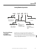
operating buttons 31
operating modes
7, 55
operation
55
operator interface
58
overview summary screen
60
P
panel mount 25
Powermonitor 1000
25
panel mounting controller
15
PanelView Component
connect power
24
PanelView Component C600
8
guidelines
19
mounting
20
mounting angle
19
mounting lever
21