
Owner's manual

Rockwell Automation Publication 1413-UM001D-EN-P - November 2010 39
Configuration Chapter 3
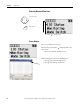
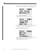
View MicroLogix 1400 Controller Ethernet Status
The Ethernet configuration screen of the LCD displays the MAC and IP
addresses assigned to the MicroLogix 1400 controller.
Follow these steps to view the Ethernet configuration for your controller.
1. On the Main Menu screen, select Advanced Set by using the Up and Down
keys on the LCD keypad, as shown below.
B3:1/8 Capacitor Step 5 - Mode Yes
(1)
0 = Manual, 1 = Auto Step Control
B3:1/9 Capacitor Step 6 - Mode Yes
(1)
B3:1/10 Capacitor Step 7 - Mode Yes
(1)
B3:1/11 Capacitor Step 8 - Mode Yes
(1)
B3:1/12 Capacitor Step 9 - Mode Yes
(1)
B3:1/13 Capacitor Step 10 - Mode Yes
(1)
B3:1/14 Capacitor Step 1 - Manual Command Yes 0 = Command Off,
1 = Command On
B3:1/15 Capacitor Step 2 - Manual Command Yes
(1)
B3:2/0 Capacitor Step 3 - Manual Command Yes
(1)
B3:2/1 Capacitor Step 4 - Manual Command Yes
(1)
B3:2/2 Capacitor Step 5 - Manual Command Yes
(1)
B3:2/3 Capacitor Step 6 - Manual Command Yes
(1)
B3:2/4 Capacitor Step 7 - Manual Command Yes
(1)
B3:2/5 Capacitor Step 8 - Manual Command Yes
(1)
B3:2/6 Capacitor Step 9 - Manual Command Yes
(1)
B3:2/7 Capacitor Step 10 - Manual Command Yes
(1)
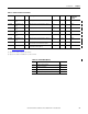
B3:2/8 Auto Configure Capacitor Step Sizes Yes Set to 1 to initiate Configuration
B3:2/9 System Alarm No 0 = No Alarm, 1 = In Alarm Alarm Summary
B3:2/10 Bad Step Alarm No
B3:2/11 Power Factor Not Achieved Alarm No
B3:2/12 Voltage Alarm No
(1) Depends on the number of capacitor steps in N7:46.
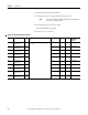
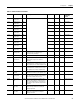
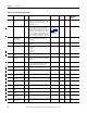
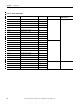
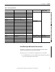
Table 11 - Binary (bit) Elements
Address Parameter Configurable Value PanelView Component
Terminal Screen