
Owner's manual


30 Rockwell Automation Publication 1413-UM001D-EN-P - November 2010
Chapter 3 Configuration
Communication Settings
The following sections provide information on configuring communication for
the components.
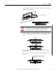
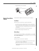
Base Unit
Communication settings are factory configured. The MicroLogix 1400
controller settings are contained in the EEPROM memory module.
PowerMonitor 1000 meter settings are stored in onboard nonvolatile memory
(NVRAM). Configuration settings are listed below.
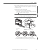
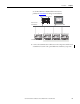
Ethernet HMI Option
This option allows the PanelView Component C600 terminal to connect to your
Ethernet network. The PanelView Component C600 Touch HMI terminal with
Ethernet communication provides ease of navigation, viewing, and configuration
of the capacitor bank controller application.
Default communication settings are factory configured.
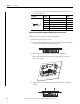
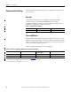
Table 7 - Communication Settings
Device/Parameter MicroLogix 1400 Controller PowerMonitor Meter 1
Protocol EtherNet/IP EtherNet/IP
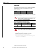
Table 8 - PanelView Component C600 Ethernet Configuration Settings
Device/Parameter MicroLogix 1400 Controller PanelView Componet C600
Operator Terminal
PowerMonitor 1000 Meter 1
(2)
IP Address 192.168.254.100
(1)
192.168.254.105 192.168.254.64
Subnet Mask 255.255.0.0 255.255.0.0 255.255.0.0
(1) See MicroLogix 1400 Controller Installation Instructions, publication 1766-UM001 for instructions on changing the controller’s IP Address. If you change the controller’s IP
Adress, make sure all of the Capacitor Bank devices are on the same network or IP Address range.
(2) The default Gateway for the PowerMonitor 1000 is 128.1.1.1.