
Owner's manual

Rockwell Automation Publication 1413-UM001D-EN-P - November 2010 11
Installation Chapter 2
Mount and Connect Your
Controller
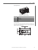
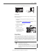
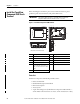
This section describes how to mount the MicroLogix 1400 controller and
connect it to a PanelView Component module for use with the capacitor bank
controller.
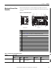
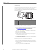
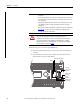
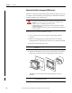
Figure 2 - Controller Description
Description
1 Comm port 2 - 9-pin D-Shell RS-232C connector
2 Memory module (refer to MicroLogix 1400 Memory Module Installation Instructions,
publication 1766-IN010
, for instructions on installing the memory module).
3 Output ±24V DC, 240 mA
4 Input terminal block
5 LCD display keypad (ESC, OK, Up, Down, Left, Right)
6 Battery compartment
7 1762 expansion bus connector
8 Battery connector
9 Output terminal block
10 LCD display
11 Indicator status indicator panel
12 Comm port 1 - RJ45 connector
13 Comm port 0 - 8-pin mini DIN RS-232C/RS-485 connector
1
ESC
OK
256 7
8
9101113 12
43
1
Left Side View Top View
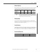
Table 4 - Controller Input and Output Description
Cat. No. Description
Input
Power
User
Power
Embedded
Discrete I/O
Embedded
Analog I/O
Comm.
Ports
1766-L32BWA 100/240V AC 24V DC,
240 mA
12 Fast 24V DC Inputs
8 Normal 24V DC Inputs
12 Relay Outputs
None 1 RS232/RS485
1 Ethernet/IP
1 RS232