User Manual Capacitor Bank Controller Catalog Number 1413-CAP
Important User Information Solid-state equipment has operational characteristics differing from those of electromechanical equipment. Safety Guidelines for the Application, Installation and Maintenance of Solid State Controls (publication SGI-1.1 available from your local Rockwell Automation sales office or online at http://www.rockwellautomation.com/literature/) describes some important differences between solid-state equipment and hard-wired electromechanical devices.
Table of Contents Preface Who Should Use This Manual . . . . . . . . . . . . . . . . . . . . . . . . . . . . . . . . . . . . . . 5 Additional Resources . . . . . . . . . . . . . . . . . . . . . . . . . . . . . . . . . . . . . . . . . . . . . . . 5 Chapter 1 General Information Introduction. . . . . . . . . . . . . . . . . . . . . . . . . . . . . . . . . . . . . . . . . . . . . . . . . . . . . . . 7 Description of the Capacitor Bank Controller . . . . . . . . . . . . . . . . . . . . . . . . 7 Functions . .
Table of Contents PowerMonitor 1000 Meter Configuration. . . . . . . . . . . . . . . . . . . . . . . . . . Parameter Descriptions. . . . . . . . . . . . . . . . . . . . . . . . . . . . . . . . . . . . . . . . Set Parameters with the PowerMonitor 1000 Unit . . . . . . . . . . . . . . Configuration with the PanelView Component C600 Terminal (optional HMI only) . . . . . . . . . . . . . . . . . . . . . . . . . . . . . . . . . . . . Capacitor Bank Commissioning Checklist . . . . . . . . . . . . . . . . . . . .
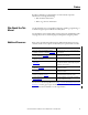
Preface Read this to familiarize yourself with the rest of the manual. It provides information concerning the following: • Who should use this manual • Where to go for more information Who Should Use This Manual Use this manual if you are responsible for designing, installing, programming, or troubleshooting the Capacitor Bank Controller system. You should have a basic understanding of electrical circuitry and familiarity with relay logic.
Preface Notes: 6 Rockwell Automation Publication 1413-UM001D-EN-P - November 2010
Chapter 1 General Information Introduction The capacitor bank controller is intended for standard, fixed-function capacitor banks. The controller consists of standard, off-the-shelf, Allen-Bradley hardware with the application ladder code necessary to perform power factor correction. The controller is designed to provide the same base functionality as a fixedfunction capacitor bank controller.
Chapter 1 General Information • Alarms – Bad step, indicates blown fuse, capacitor failure – Target power factor not achieved – High / Low voltage – Metering – Communication loss • PowerMonitor data concentrated into the MicroLogix 1400 controller • Phase current, line voltage, frequency, real and reactive power, and power factor Options • Up to three additional PowerMonitor 1000 meters to aggregate up to four total feeds • The PanelView Component C600 Touch HMI terminal with Ethernet communication provi
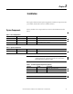
Chapter 2 Installation The capacitor bank controller system is supplied as a number of components that you assemble, install, and connect in a suitable enclosure. System Components The key number in the component lists are referenced in the illustrations that follow. Table 1 - Base Configurations Key Quantity Cat. No.
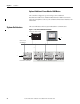
Chapter 2 Installation Optional Additional PowerMonitor 1000 Meters The controller is designed to operate with up to three additional PowerMonitor 1000 meters. Additional PowerMonitor 1000 meters must be ordered separately. Please contact your local Rockwell Automation distributor for information. System Architecture This section illustrates the base system with Ethernet communication.
Installation Mount and Connect Your Controller Chapter 2 This section describes how to mount the MicroLogix 1400 controller and connect it to a PanelView Component module for use with the capacitor bank controller.
Chapter 2 Installation Mount the Controller Most applications require installation in an industrial enclosure to reduce the effects of electrical interference and environmental exposure. Locate your controller as far as possible from power lines, load lines, and other sources of electrical noise such as hard-contact switches, relays, and AC motor drives. For more information on proper grounding guidelines, see the Industrial Automation Wiring and Grounding Guidelines, publication 1770-4.1.
Installation Chapter 2 Mounting Dimensions C A B 1766-L32BWA, 1766-L32AWA, 1766-L32BXB, 1766-L32BWAA, 1766-L32AWAA, 1766-L32BXBA Dimension Height A 90 mm (3.5 in.) B 180 mm (7.087 in.) C 87 mm (3.43 in.) Controller Spacing The controller mounts horizontally, with the expansion I/O extending to the right of the controller. Allow 50 mm (2 in.) of space on all but the right side for adequate ventilation, as shown below.
Chapter 2 Installation DIN Rail Mounting The maximum extension of the latch is 14 mm (0.55 in.) in the open position. A screwdriver is required for removal of the controller. The controller can be mounted to EN50022-35x7.5 or EN50022-35x15 DIN rails. DIN rail mounting dimensions are shown below. B A C Dimension Height A 90 mm (3.5 in.) B 27.5 mm (1.08 in.) C 27.5 mm (1.08 in.) Follow these steps to install your controller on the DIN rail. 1. Mount your DIN rail.
Installation Chapter 2 4. Unhook the top of the DIN rail slot from the rail. ESC OK Open Closed Panel Mounting Mount to panel by using #8 screws. Follow these steps to install your controller with mounting screws. 1. Remove the mounting template from inside the back cover of this document. 2. Secure the template to the mounting surface, making sure your controller is spaced properly (see Controller Spacing on page 13 for more information). 3. Drill holes through the template. 4.
Chapter 2 Installation IMPORTANT The MicroLogix 1400 controller ships with the battery wire connector connected. Be sure that the battery wire connector is inserted into the connector port if your application needs battery power. For example, when using a realtime clock (RTC). Replacing the battery when the controller is powered down will lose all user application memory. Replace the battery when the controller is powered on.
Installation Chapter 2 Wire the MicroLogix 1400 Controller Follow the diagram to wire the MicroLogix 1400 controller to the capacitor bank controller.
Chapter 2 Installation Install the PanelView Component C600 Touch Terminal Before installing the terminal in a panel, review minimum clearances, panel guidelines, panel cutout dimensions, and product dimensions. IMPORTANT The capacitor bank controller is compatible with the PanelView Component C600 terminal firmware revision 1.3 or later.
Installation Chapter 2 Minimum Spacing Plan for adequate space around the terminal, inside the enclosure, for ventilation and cabling. Consider heat produced by other devices in the enclosure. The ambient temperature around the terminal must be 0…50 °C (32…122 °F). PanelView Component Top Bottom Sides Back C200 and C300 Keypad C600 Touch 51 mm (2 in.) 51 mm (2 in.) 25 mm (1 in.) 13 mm (0.5 in.
Chapter 2 Installation Mount the PanelView Component C600 Terminal PanelView Component C600 terminals install easily in a panel without any tools or hardware. The terminals have panel clamps that automatically latch when the terminal is pushed into the panel opening. ATTENTION: • Disconnect all electrical power from the panel before making the panel cutout. • Make sure the area around the panel cutout is clear.
Installation Chapter 2 These views show the panel clamps fully extended to secure the terminal against the rear of the panel. Fully extended panel clamps 6 1 6 1 ATTENTION: Follow the instructions to provide a proper seal and to prevent potential damage to the terminal. Allen-Bradley assumes no responsibility for water or chemical damage to the terminal or other equipment within the enclosure because of improper installation. 5.
Chapter 2 Installation Use this table as a guide to provide an adequate gasket seal between the terminal and the panel. Terminal Markings for Alignment 6 1 Lever Position Panel Thickness Range Typical Gauge 1 1.52…2.01 mm (0.060…0.079 in.) 16 2 2.03…2.64 mm (0.08…0.104 in.) 14 3 2.67…3.15 mm (0.105…0.124 in.) 12 4 3.17…3.66 mm (0.125…0.144 in.) 10 5 3.68…4.16 mm (0.145…0.164 in.) 8/9 6 4.19…4.75 mm (0.165…0.187 in.
Installation Chapter 2 Before reinstalling the terminal in the panel opening, you must release each panel clamp from its locked position. Do this as soon as possible after the removing the terminal from the panel. Follow these steps to unlock each panel clamp. 1. Insert the tip of a #3 - #6, screwdriver, approximately 5 mm (0.20 in.), into the location shown on each clamp, next to the arrow icon , and pull the screwdriver straight out.
Chapter 2 Installation Connect Power The PanelView Component terminal connects to a customer supplied 24V DC, 10 W (minimum) power source(1). The table shows the power rating. Table 5 - Power Ratings PanelView Component Input Voltage Range Power Consumption, Max C600 18…30V DC (24V DC nom) 10 W (0.42 A) The internal, nonisolated power supply is protected against reverse polarity of the DC+ and DC- connections.
Installation Chapter 2 4. Apply 24V DC power to the terminal. DC+ Mount the PowerMonitor 1000 Unit DC- Functional Earth Ground to Ground Bus The PowerMonitor 1000 unit can be mounted on a panel or a DIN rail. Panel Mount Follow these steps to mount the unit on a panel or any flat surface. 1. Extend the top and bottom DIN-rail clips to the panel mount position. 2.
Chapter 2 Installation Remove from a DIN Rail Follow these steps to remove the unit from a DIN-rail. 1. Insert a small screwdriver into the exposed slot in the tab to remove the unit from the DIN rail. 2. Pull enclosure forward and remove from the rail. Connect the Controller, PanelView Component Terminal, and the PowerMonitor 1000 Meter Follow these steps to connect the Capacitor Bank controller parts. 1. Connect a source of 120/230V AC to the control power terminals on the MicroLogix 1400 controller.
Installation Chapter 2 See the PowerMonitor 1000 Installation Instructions, publication 1408-IN001 for wiring recommendations.
Chapter 2 Installation Notes: 28 Rockwell Automation Publication 1413-UM001D-EN-P - November 2010
Chapter 3 Configuration Overview The capacitor bank controller base unit has been set up to require minimal outof-box configuration. The base system has default communication settings. Certain circumstances and options require additional communication configuration, which may include the use of programming software not included with the controller. You are required to configure the PowerMonitor 1000 meters to coordinate them to the power circuit in the base unit and all options.
Chapter 3 Configuration Communication Settings The following sections provide information on configuring communication for the components. Base Unit Communication settings are factory configured. The MicroLogix 1400 controller settings are contained in the EEPROM memory module. PowerMonitor 1000 meter settings are stored in onboard nonvolatile memory (NVRAM). Configuration settings are listed below.
Configuration MicroLogix 1400 Controller Chapter 3 This section describes how to use the LCD and keypad on the MicroLogix 1400 controller. Operating Buttons ESC Button Function Cursor Buttons Move cursor Select menu item Choose file numbers, values, etc. OK Next menu level, store your entry, apply the changes ESC Previous menu level, cancel your entry OK Using Menus to Choose Values Press To • Go to next menu level. • Store your entry. • Apply the changes. OK ESC • Go to previous menu level.
Chapter 3 Configuration Selecting Between Menu Items Cursor up or down Apply or Enter OK The symbol " " is used as the cursor. Cursor Display There are two different cursor types: Selection cursor (the symbol “ ”) is displayed left to the selected item.
Configuration Chapter 3 Setting Values Change value = up/down arrows Move cursor between digits = left/right arrows Stores Entries OK ESC Retain previous value Left/right arrow moves the cursor between the digits of the value . Up/down arrow changes the value. Up arrow = increment Down arrow = decrement Controller Configuration You may view and edit the Capacitor Bank Controller parameters by using the LCD interface.
Chapter 3 Configuration 2. Press the Enter key to edit the parameter. 3. Use the up/down keys to change the value of the parameter. TIP If the data is protected or undefined, pressing the up/down key scrolls to the next data element. 4. Press the Enter key to store the new value. Esc key will discard the new value. 5. Repeat steps 2…5 as needed.
Configuration Chapter 3 Table 9 - Control and Status Parameters Address Parameter Unit Description Configurable Range Default PanelView Component Screen N7:10 Capacitor Step 1 Effective Size kVAR Nameplate capacitor size for each step Yes 50 Configuration N7:11 Capacitor Step 2 Effective Size kVAR Yes(2) 50 Configuration N7:12 Capacitor Step 3 Effective Size kVAR Yes(2) 50 Configuration N7:13 Capacitor Step 4 Effective Size kVAR Yes(2) 50 Configuration N7:14 Capacitor Step
Chapter 3 Configuration Table 9 - Control and Status Parameters Address Parameter Unit N7:42 Voltage In-Range Time seconds The amount of time after the Voltage High and Voltage Low alarms have been reset, before signifying that the voltage is in an acceptable range N7:43 Control Word(1) This is the control word for the capacitor bank controller. Bit 4 is used to initiate a restore of factory defaults. This should be treated as a momentary state. Bit 5 is used to initiate the step size buffer.
Configuration Chapter 3 Table 9 - Control and Status Parameters Address Parameter N139:35 Unit Description Configurable Range Default PanelView Component Screen PowerMonitor 3 IP Byte C 3rd byte (octet) of PowerMonitor IP Address Yes(3) 0…255 254 Admin N139:36 PowerMonitor 3 IP Byte D 4th byte (octet) of PowerMonitor IP Address Yes(3) 0…255 66 Admin N139:42 PowerMonitor 4 IP Byte A 1st byte (octet) of PowerMonitor IP Address Yes(3) 0…255 192 Admin N139:43 PowerMonitor 4 IP Byt
Chapter 3 Configuration Table 11 - Binary (bit) Elements Address Parameter Configurable Value PanelView Component Terminal Screen B3:0/0 Capacitor Step 1 - Status No 0 = Off, 1 = On Bank Status B3:0/1 Capacitor Step 2 - Status No B3:0/2 Capacitor Step 3 - Status No B3:0/3 Capacitor Step 4 - Status No B3:0/4 Capacitor Step 5 - Status No B3:0/5 Capacitor Step 6 - Status No B3:0/6 Capacitor Step 7 - Status No B3:0/7 Capacitor Step 8 - Status No B3:0/8 Capacitor Step 9 - Status
Configuration Chapter 3 Table 11 - Binary (bit) Elements Address Parameter Configurable Value PanelView Component Terminal Screen B3:1/8 Capacitor Step 5 - Mode Yes(1) 0 = Manual, 1 = Auto Step Control B3:1/9 Capacitor Step 6 - Mode Yes(1) B3:1/10 Capacitor Step 7 - Mode Yes(1) B3:1/11 Capacitor Step 8 - Mode Yes(1) B3:1/12 Capacitor Step 9 - Mode Yes(1) B3:1/13 Capacitor Step 10 - Mode Yes(1) B3:1/14 Capacitor Step 1 - Manual Command Yes B3:1/15 Capacitor Step 2 - Manual Comm
Chapter 3 Configuration If the menu items shown in the figure below are not displayed on the Main Menu screen, you need to scroll down the screen by pressing the Down key. 2. Press the OK key on the LCD keypad. The Advanced Set Menu screen is displayed, as shown below. 3. If ENET Cfg is selected, press the OK key, otherwise, select ENET Cfg by using the Up and Down keys, and then press the OK key. The Ethernet Configuration screen is displayed. 4. Press the OK key on the LCD Status menu.
Configuration Chapter 3 A MAC address is a 12-digit hexadecimal number. Your controller ships with a unique MAC address assigned in the factory. You can identify the MAC address of your controller by opening the expansion module cover on your controller. When an IP address is assigned to your controller, both the MAC and IP addresses of your controller are displayed, as shown below. In this example, the MAC address is represented as XXXXXXXXXXXX. The IP address is represented as xxx.xxx.xxx.
Chapter 3 Configuration PowerMonitor 1000 Meter Configuration The table below lists the configuration parameters that must be set up for correct operation of the capacitor bank controller. For additional information regarding PowerMonitor 1000 meter configuration, please refer to the PowerMonitor 1000 User Manual, publication 1408-UM001. Table 12 - PowerMonitor Meter Configuration Parameters Parameter PowerMonitor 1 PowerMonitor 2 PowerMonitor 3 PowerMonitor 4 IP address 192.168.254.64 192.168.
Configuration Chapter 3 Parameter Descriptions • Wiring mode – selected to match the physical connections to the power system – Direct Delta – Open Delta – Wye – Single phase – 1 PT 1 CT - LL – 1 PT 1 CT - LN • PT (VT) primary voltage – reflects the voltage rating on the high side of the potential/voltage transformers. Range 1…50,000V, default 480V • PT (VT) secondary voltage – reflects the voltage rating on the low side of the potential/voltage transformers.
Chapter 3 Configuration Table 13 - Button Function Button Mode Display Program Edit Escape Returns to parent menu At top menu, selects default screen Cancels changes to the parameter and returns to Program mode Up arrow Steps back to the previous parameter or menu item Increments the value of the highlighted digit Down arrow Steps forward to the next parameter or menu item Decrements the value of the highlighted digit Enter Steps into a sub-menu or sets default screen Steps into a submenu,
Configuration Chapter 3 LCD Screen Display and Configuration Menu Map Figure 6 - Main Menu, Page 1 Default Screen? Level 1 Display Program Password? Level 2 Display Config Setup Display Metering Level 3 Metering Volts Amps Frequency(1) Metering Power(1)(2) Metering Energy(1) See Setup Submenu Level 4 I1 I2 I3 I Average V LN1 V LN2 V LN3 V L12 V L23 V L31 V LN Avg V LL Avg Frequency Unbalance V Unbalance I PF 1 PF 2 PF 3 PF Total KW 1 KW 2 KW 3 KW Total KVAR 1 KVAR 2 KVAR 3 KVAR Total KVA 1 KVA 2
Chapter 3 Configuration Default Screen The PowerMonitor 1000 unit lets you select and navigate to a default screen. The default screen displays at startup and is displayed after the display has been dormant for approximately 30 minutes. To set the current screen as the default, press Enter and click Yes. If you’re in another menu and want to get back to the default screen, continue pressing Escape until you are prompted To Default Screen? Click Yes to display the default screen.
Configuration Chapter 3 Edit a Parameter Follow these guidelines to edit a parameter: • Press or to change the highlighted digit. • Press and together to move the highlight cursor one place to the left, and press or to set the selected digit’s value. Continue in the same way until the correct value is entered then press when done.
Chapter 3 Configuration Configure the capacitor bank controller by using the optional PanelView terminal. 1. Press Menu to view the Menu from the Overview screen. 2. Press Configuration to view the Configuration screen from the Menu. In this screen you can configure: • the number of steps. The default value is 10; that will show all 10 steps. Num Step is between 1 and 10. • Number of PowerMonitors from 1…4. Default is 1. At least one PowerMonitor unit must be configured. • Steps in kVAR.
Configuration Chapter 3 5. Press Auto Detect kVAR to navigate to the Auto Configure Effective kVAR process. TIP The number of measurements to average for each step is entered on the Extended Configuration Screen #2 (F10). 6. Follow steps 1…3 on this screen, then press Auto Detect Cap Size to initiate the auto-configuration process. 7. Navigate to the Extended Status screen and write down the Measured kVAR for each of your capacitor banks. 8.
Chapter 3 Configuration 9. Navigate to Menu then to Extended Configuration 1. This screen operates in the same way as the initial configuration screen. These guidelines apply in the Configuration screen: • Nominal Volts is a number between 0 and 9999 using the scale 1/10/100/1000. Therefore, a voltage of 13,400V would be entered as 1340. • Volt Range % is used for voltage high/low alarms. • Timer preset is for high and low values for the high/low voltage alarms.
Configuration Chapter 3 11. Set the Step Control to Manual or Auto. This screen shows the step control of the Capacitor Bank controller. Step Control screens let you place a step in Auto (A) or Manual (M) mode. When using the Balanced, Best Fit, or FILO operating mode, make sure all the steps are in Auto mode. Just pressing the step will toggle the step in Auto (A) or Manual (M) mode. The first row (from the left) is to configure the step; the second row is the status of step (A or M).
Chapter 3 Configuration 12. Navigate to Menu then to Operating Mode and select your operating mode. This screen shows the Operating mode. Verify your steps are configured properly before making Operating mode selections: • Manual (mode = 0) – This mode disables all automatic operating modes. Manual mode is the default configuration. All capacitor steps have a default configuration of auto.
Configuration Chapter 3 13. Navigate to Menu then to ADMIN Screen. The Admin screen provides the IP address of the PowerMonitor units used in the Capacitor Bank controller. The default IP address for the Powermointor 1000 unit in this application is 192.168.254.64. After changing the IP address, you must press Config IP for the controller to change the IP address in the explicit messaging. ATTENTION: Changing the IP address causes all of the capacitors to turn off and that can cause a power disturbance.
Chapter 3 Configuration As a minimum, the following configurations are required. • Configuration is the number of steps configured with Discharge time, lead and/or lag settings. • Configuration 1 and 2 are Nominal voltage, Voltage high/low limits, Powerfactor timers, samples to average, and Input modes. • Step Control configures all the steps in the appropriate mode. • Operating mode is one of the three Automatic modes, FILO, Balanced, or Best Fit.
Chapter 4 Operation Introduction The capacitor bank controller gathers real- and reactive-power data by using one or more PowerMonitor meters. The processor manipulates data in engineering units of kVAR and kW. The unit does not directly control power factor, but rather works to actively minimize imported and exported kVAR. The net result of this philosophy indirectly controls power factor and minimizes voltage excursions associated with excessive kVAR export.
Chapter 4 Operation • Balanced (mode = 2) – This mode counts the number of opening operations on each capacitor step and switch-capacitor steps to balance the number of opening operations equally across all of the employed capacitor steps. This mode is also most useful when all of the steps are of similar size. • Best Fit (mode = 3) – This mode selects capacitor steps to be switched on and off to most closely achieve the target power factor and kVAR needs of the system.
Operation Chapter 4 Figure 9 - Controller Wiring Diagram COM 0 IN7 IN8 Fault Relay 10 Fault Relay 8 COM 1 IN2 Fault Relay 7 Fault Relay 5 IN5 IN1 IN3 IN4 IN6 VAC L2/N OUT0 OUT1 OUT2 Reset Fault Relay 9 Fault Relay 4 Fault Relay 3 Fault Relay 1 IN0 Fault Relay 6 Fault Relay 2 Master Fault Relay Capacitor Step Contactors or Interposing Relays IN10 COM 2 COM 3 IN15 IN13 IN19 IN17 IN9 IN11 IN12 IN14 IN16 IN18 OUT4 VAC DC5 OUT7 OUT8 OUT10 COM ANA IV0(+) COM ANA I
Chapter 4 Operation Alarms The capacitor bank controller offers these alarms: • Bad Step - This alarm indicates a blown fuse and/or loss of capacitor condition. The controller measures actual VAR output from a capacitor step, averages, and compares this value with the original effective capacitor value. When actual VAR is more than the user-configurable StepKvarTolerance (default 5%) below the effective step size for a userconfigurable delay (default 30 seconds), the alarm is activated.
Operation Chapter 4 Optional PanelView Component C600 HMI The optional PanelView Component C600 HMI provides you with a user interface. During operation these screens are provided: • Overview Summary • Navigation/Menu • Bank Status • Extended Status • Step Control • Power Factor Summary • Powermonitoring Data x4 • Alarm Summary • System Configuration These status screens show the operation of the capacitor bank controller.
Chapter 4 Operation Screen Navigation Tree Overview Summary Navigation/ Menu Step Status Power Factor Summary PowerMonitor 1000 #1 Data Alarm Summary Configuration Extended Status PowerMonitor 1000 #2 Data (optional) Extended Configuration Step Control PowerMonitor 1000 #3 Data (optional) Extended Configuration 2 PowerMonitor 1000 #4 Data (optional) Overview Summary Screen This is the home screen and displays after you apply power. Press Menu to navigate to the Menu screen.
Operation Chapter 4 Navigation/Menu Screen Bank Status Screen The status for the steps is listed in vertical columns from 1…10. There are no configurations on this screen. It displays status data only. Mode: A = Automatic, which means the step is controlled based on the operation mode selected. M = Manual, which means you can force the step on or off via the keypad. Step Status: 1 = On, 0 = Off. Discharge Status: ‘ ’ = Not Discharging, D = Discharging. Alarm: ‘ ’ = No Alarm, ‘A’ = In Alarm.
Chapter 4 Operation Extended Status Screen Press Reset Counters to navigate to the Reset Counters screen. There are no other user-configurable fields on this screen. Press Menu and then Overview to return to the Overview Summary Screen. Power Factor Summary Screen There are no user-configurable fields on this screen. Press Menu then Overview to return to the Overview Summary Screen.
Operation Chapter 4 Alarms are listed in the center of the screen. Alarms can be cleared at the PLC or HMI level by using the corresponding buttons on this screen. Press Menu then Overview to return to the Overview Summary Screen. PowerMonitor Meter Screen There are four instances of this screen, one for each of the PowerMonitor meters. There are no user-configurable fields on this screen. Use the navigation buttons on the bottom of the screen to navigate to each PowerMonitor Data Screen.
Chapter 4 Operation Notes: 64 Rockwell Automation Publication 1413-UM001D-EN-P - November 2010
Chapter 5 SCADA Interface Power-circuit Parameters The capacitor bank controller reads power-circuit parameters from the PowerMonitor meters and makes that data available in its data table for use by other applications such as SCADA or HMI systems. This table lists the PowerMonitor meter data available in the controller. The symbol x indicates the PowerMonitor meter number. Addresses related to PowerMonitor meter no. 1 begin with F11:0, addresses related to PowerMonitor meter no. 2 begin with F12:0.
Chapter 5 SCADA Interface Additional data is available in systems with the Ethernet PowerMonitor meter option. In these systems, all PowerMonitor meter data may be accessed by using the Ethernet communications port integral to the PowerMonitor meter. Please refer to the PowerMonitor 1000 User Manual, publication 1408-UM001, for further information.
Appendix A Catalog Number Explanation 1413 - CAP - ME - PE C Bulletin Number Series 1413 - Power and Energy Controllers Base Unit Type Type of Device CAP - Capacitor Bank Controller Base Unit with Ethernet 1413-CAP-ME PowerMonitor Meter ME Communicate with one Ethernet PowerMonitor 1000 C - Series C Additional HMI PE - Ethernet PanelView Component C600 This includes a base controller and one PowerMonitor 1000 meter on the Ethernet network. Note that ME = Ethernet meter communication.
Appendix A Catalog Number Explanation Ethernet Base Unit with 1413-CAP-ME-PE Ethernet HMI To add PanelView Component C600 terminal to the system, add PE to the catalog number. A PE indicates HMI with Ethernet communications. This option includes a PanelView Component terminal as the HMI to configure or view the capacitor bank controller in addition to the MicroLogix 1400 controller and the PowerMonitor 1000 meter. This option provides access for quick configurations. Table 15 - Summary 68 Cat. No.
Glossary The following terms and abbreviations are used throughout this manual. For definitions of terms not listed here, refer to the Allen-Bradley Industrial Automation Glossary, publication AG-7.1. Bank An overall capacitor or tuned-filter assembly. This controller is designed to manage and control one bank consisting of 10 steps. Instance An instance of an object represents a complete iteration of an object and all of its attributes and methods.
Glossary Notes: 70 Rockwell Automation Publication 1413-UM001D-EN-P - November 2010
Index A additional Powermonitors 10 additional resources 5 alarm summary screen 62 alarms 8, 58 status 39 extended status screen 62 F functions 7 B bank status screen 61 battery 15 connection 16 disposal 15 buttons 31 C catalog number explanation 67 communication configuration 30 base unit 30 Ethernet HMI option 30 configuration 29 Powermonitor meter 42 connect controller 11 PanelView Component C600 Ethernet 18 controller battery 15 dimensions 13 DIN rail mounting 14 location 12 panel mounting 15 spacin
Index panel cutout dimensions 19 parts list 18 removal 22 spacing 19 unlock panel clamp 23 PanelView Component C600 Ethernet 18 power factor summary screen 62 power supply 9 power-circuit parameters 65 Powermonitor 1000 7 button function 44 configuration 42 DIN rail mount 25 edit parameter 47 menu map 45, 46 menu navigation 44 panel mount 25 parameter descriptions 43 screen 63 set parameters 43 sub menu 46 menu navigation 44 sub menu 46 system architecture 10 Ethernet options 10 system components 9 system
Notes:
Notes:
Rockwell Automation Support Rockwell Automation provides technical information on the Web to assist you in using its products. At http://www.rockwellautomation.com/support/, you can find technical manuals, a knowledge base of FAQs, technical and application notes, sample code and links to software service packs, and a MySupport feature that you can customize to make the best use of these tools.