installation and operation Manual
Manuals
Brands
Rockwell Automation Manuals
Equipment
140U Q, M frame CB Electronic RMS Trip Unit
1
2
3
4
5
6
7
8
9
10
Page
4
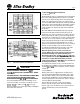
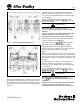
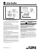
Fig.
5
SOURCE
LOAD
.Aux~Iiary
switch
shown
m
the
"
Breaker
Canlacis
Open''
pmilmn
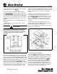
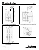
Fig.
6
-
COVER
SCREWS
TORQUE
20-22
9
9
-1b
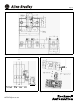
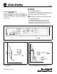
Fig.
7a
M-Frame
Trip
Unit
Installation
40752-072(2)
Effective
6/02
1
...
2
3
4
5
6
...
...
14