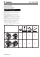
Bul. 140G/140MG 140G-R_ Installation instruction for 140G-R Istruzioni di installazione Installationsanleitung Instructions pour l’installation Instrucciones de instalación Installation - Installazione - Instalación Instalação WARNING: To prevent electrical shock, disconnect from power source before installing or servicing. Install in suitable enclosure. Keep free from contaminants. (Follow NFPA70E requirements).
Index 1. Description.................................................................. 3 11. 1.1 1.2 General characteristics.......................................................... 3 External front view of the circuit-breaker.............................. 3 2. Checking on receipt.................................................... 3 11.1 Safety notes........................................................................ 20 11.1.1. Notes for dielectric strength tests...........................
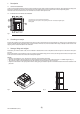
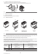
1. Description 1.1 General characteristics 140G-R circuit-breakers and disconnectors consist of a plastic structure which houses the operating mechanism, the poles and the auxiliary parts. Each pole is insulated from the others and contains the circuit breaking parts and the current sensor of the corresponding phase. The fixed version circuit-breaker has its own terminals for connection to the power circuit. 1.
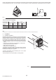
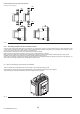
Comply with the following instructions when lifting the circuit-breaker: the circuit-breakers must be placed on a sturdy surface and preferably lifted with an appropriate fork-lift truck. The use of ropes is, however, permitted: In this case, the lifting ropes ust be attached as shown in the figure. Fig.
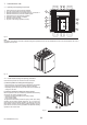
4.2 Installation of the flange on the compartment door (Fig. 8) – Drill the holes in the compartment door indicated in the section entitled “Overall dimensions”. – Apply the flange (1) to the front of the compartment door and fix it from the inside with the self-tapping screws (2). 2 1 Fig. 8 5. Electrical connections 5.1 Power circuit connections Use insulated bars/ perform specific type tests on the installation. 5.1.
Positioning the first anchor plate of the busbars Anchoring to the switchboard 190 7.48" 190 7.48" 190 7.48" 190 7.48" 190 7.48" 190 7.48" Fig. 11 5.2.3 Assembly procedures for the connection busbars Check the state of the contact surfaces of the connections very carefully: they must be very clean and free from burrs, dents and traces of rust - which must be removed with a fine file or emery cloth to prevent localized increases in temperature.
6. Putting into service 6.1 General procedures – Make sure that the power connections to the circuit-breaker terminals are tight – Perform al the preparatory operations on the release – Make sure that the power supply voltage of the auxiliary circuits is between 85% and 110% of the rated voltage of the electrical applications – To avoid temperature rises, make sure that there is sufficient air exchange in the installation area – Also perform the inspections indicated in the following table.
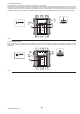
7. Instructions for use 7.1 Operating and signalling components 1 Push-button for the manual opening operation 2 Lever for manual loading of the closing springs 3 Mechanical indicator for circuit-breaker open “O” and closed “I” 4 Mechanical indicator for protection release tripped 5 Pushbutton for the manual closing operation 6 Indicator for springs loaded - unloaded 7 Operation counter (to order) 8 Key lock on the closing operation (to order) 4 8 5 1 6 2 3 7 Fig.
c) Circuit-breaker closing This operation can only be carried out when the closing springs are fully loaded. Press the push-button (5) marked with the letter “I” for closing in the manual mode. When there is a shunt closing release, the operation can also be carried out in the remote mode by means of the special control circuit. Closing is signalled by the relative indicator (3), which moves to the “I” position. Moreover, the indicator of the state of the springs (6) moves to the WHITE position.
8. Maintenance 8.1. Warnings WARNING: before proceeding with any maintenance operation, it is obligatory to: --Oen the circuit-breaker and make sure that the springs of the operating mechanism are unloaded; --if work must be performed on fixed circuit-breakers or on fixed parts, disconnect the power supply to the power circuit and auxiliary circuits and visibly earth the terminals on both the supply side and load side; --Set the equipment to safe conditions as established by the standards and laws in force.
8.3.1. Preliminary operations: --open the circuit-breaker and make sure that the springs of the operating mechanism are unloaded. WARNING: if work must be performed on the circuit-breakers, disconnect the power circuit and auxiliary circuits and earth the terminals in a visible way on both the supply side and load side. 8.3.2. General inspections and cleaning: --Check to make sure that the device is clean.
--If the undervoltage release is installed, disassemble the coil support and unload the springs of the operating mechanism by closing and opening the circuit-breaker. Fig. 20 8.3.5. Mechanical operating mechanism --Clean the points indicated in figure 21. Use a cleaning product such as Henkel’s 273471 or equivalent if there is a heavy coating of dirt. --Lubricate the opening and closing latches and the shafts in the points indicated in figure 21.
8.3.7. Protection releases ---Power the protection release with a battery unit. --Make sure that the protection release functions correctly: release test with the “Trip Test”. --Make sure that the front leds do not indicate the presence of alarms. --Make sure that the cables are correctly connected to the release modules and to the release itself (if applicable). --Remove the battery unit from the relay upon termination. 8.3.8.
8.4. Second Level maintenance operations 8.4.1. Preliminary operations: --open the circuit-breaker and make sure that the springs of the operating mechanism are discharged. WARNING: if work must be performed on the circuit-breakers, disconnect the power circuit and auxiliary circuits and earth the terminals in a visible way on both the supply side and load side. 8.4.2. General inspections and cleaning: --Check to make sure that the device (interrupting part) is clean.
--If the undervoltage release is installed, disassemble the coil support and unload the springs of the operating mechanism by closing and opening the circuit-breaker. Fig. 26 8.4.5. Mechanical operating mechanism --Clean (use a cleaning product such as Henkel’s 273471 or equivalent if there is a heavy coating of dirt) and lubricate (in the points indicated in figure 27, det. A, as per the First Level) the shafts and opening closing latches.
8.4.6. Electrical and mechanical accessories --Make sure that the accessories are securely fixed to the circuit-breaker. --Make sure that the electrical accessories are correctly connected to the circuit-breaker. --Gearmotor: after every 10000 operations, check the brushes for wear and replace the gearmotor if necessary. --Make sure that the releases (opening/undervoltage/closing) are in good conditions (absence of excessive wear, overheating, breakages) Fig. 28.
9.
10. Accessories 10.1 Electrical accessories Shunt opening / closing release (YO/YC) Allows the device to be opened or closed by remote control. Given the characteristics of the circuit-breaker operating mechanism, opening (with the circuit-breaker closed) is always possible, whereas closing is only possible when the closing springs are loaded. Most of the releases can operate with both direct and alternate current. This release provides an instantaneous service (*), but can be supplied permanently (**).
Gearmotor for automatic loading of the closing springs (M) Automatically loads the closing springs of the circuit-breaker's operating mechanism. Once the circuit-breaker has closed, the gearmotor immediately begins to reload the closing springs. The closing springs can still be loaded in the manual mode (using the relative lever of the operating mechanism) in a power failure or during maintenance work.
11. Protection releases - References The 140G-R circuit-breaker can be accessorized with LSIG protection release. Details about the operation of the relays are given in the following documents: 1000587R0001 Operating instructions for the protection releases of 140G-N, 140G-NS and 140G-R circuit-breakers 1000592R0001 LSIG Getting started 11.
12. Overall dimensions Version with front terminals 2000A (80% and 100% rated)/2500A (80% rated) N N Key 1 Inside edge of compartment door 2 Drilled M8 holes for fixing circuitbreaker (use M8 screws) 3 Insulating or insulated metal wall 5 No.2 holes for IP54 protection 6 Panle door internal plane reference 7 No.2 holes for door interlock (use M5 screws) Fig.
Version with extended front terminals 2000A/2500 - (Terminals not UL listed) 3 1 N N 2 2 Key 1 Inside edge of compartment door 2 Drilled M8 holes for fixing circuitbreaker (use M8 screws) Note: For mechanical lock for compartment door dimensions refer to overall dimensions of 140G-R with front terminals Fig.
Version with adjustable rear terminals in flat bar 2000A (80% and 100% rated)/2500A (80% rated) 3 1 N N 2 2 Key Note: For mechanical lock for compartment door dimensions refer to overall dimensions of 140G-R with front terminals Fig.
Version with vertical rear terminals 2500A (100% rated)/3000A (80% and 100% rated) 3 1 N N 2 2 Key Note: For mechanical lock for compartment door dimensions refer to overall dimensions of 140G-R with front terminals Fig.
Compartment dimensions Holes drilled in compartment door Depth 3 POLES 4 POLES Fig.36 Fig.37 Insulation distances for installation in metal cubicle Fig.
13. Circuit diagrams WARNING: Carefully read notes F and O on the circuit diagrams before installing the circuit-breaker. OPERATING STATE SHOWN The diagram illustrates the components in the following conditions: - circuit-breaker open - circuits de-energized - releases not tripped - motor operator with unloaded springs. VERSIONS Version without overcurrent release The applications indicated in figures 13, 14, 41, 42, 43, 44, 45, 46, 62 cannot be provided with this version.
IEC 60950 (UL 1950) or equivalent, able to guarantee a common mode current or leakage current (see IEC 478/1, CEI 22/3) of no more than 3.5mA, IEC 60364-41 and CEI 64-8. U) The shield of the connection cable must be earthed on the circuit-breaker side only. The connection must be made with shielded two-wire cable (the BELDEN 3105A type) no more than 15 meters in length. Z) Short-circuit T5 and T6 if the outside neutral current sensor (UI/N) is not connected.
Circuit diagram - Operating state Three-pole circuit-breaker with LSIG electronic release Four-pole circuit-breaker with LSIG electronic release Z U Motor operator, opening, closing and undervoltage releases U DIR 1000682R0002 (L5757) (28)
Signalling contacts Auxiliary circuits of releases LSIG 41 F) + * WARNING: read note F ATTENZIONE: vedere nota F ACHTUNG: Anmerkung F ATTENTION: lire remarque F ATENCIÓN: leer la nota F A4 Uaux. F) ATTENZIONE: vedere nota F WARNING: read note F ACHTUNG: Anmerkung F ATTENTION: lire remarque F ATENCIÓN: leer la nota F + Uaux.