
User Manual

DIR 1000587R0002 (L3821)
(13)
3.1.2.2 Auxiliary power supply
Externalauxiliarypowersupplyisprovidedusingagalvanically-separatedpowerpack.
Since auxiliary voltage needs to be isolated from the ground, “galvanically separated converters” in accordance with IEC
standard 60950 (UL 1950) or equivalent IEC 60364-41 and CEI 64-8, have to be used to guarantee a current in common mode
or leakage current (as dened in IEC 478/1 and CEI 22/3) no greater than 3.5 mA.
Presenceoftheauxiliarypowersupplyenablestherelayunittobeusedevenwiththecircuitbreakeropen,aswellaspoweringallthemodules.
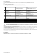
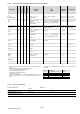
Thecharacteristicsofthepowerpackaregiveninthetablebelow.
Characteristics LSIG-MM Version
Auxiliaryvoltage
(galvanicallyseparated) 24VDC±20%
Maximumripple 5%
Inrushcurrent@24V ~2Afor5ms
Ratedpower@24V ~3W
3.1.3 Environmental characteristics
Operatingtemperature -25°C...+70°C
Storagetemperature -40°C...+90°C
Relativehumidity 0%...98%withcondensation
Degreeofprotection(withLSIG-MMinstalledintheCB) IP30
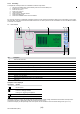
3.1.4 Description of input/output
3.1.4.1 Binary input
-K14/K15: thisinputallowsactivatingMMprotection.
TheinputisconnectedonK14andK15connectors.
Thesignalis0(MMnotactive)...24V(MMactive)
Itisimportanttofullltherightpolarity:
K14(+)
K15(-)
3.1.4.2 Binary output
-95S/98S: thisoutputgivesafeedbackonMMprotectionstatus.
IfMMprotectionisactive,thecontactisclosed,otherwiseisopen.
3.1.5 Communication bus
Externalsystembus,RS485physicalinterface,ModbusRTUprotocol,baudrate9600-19200bps.
3.1.6 Protection functions
TheLSIG-MMunitscarryoutthefollowingindependentprotectionfunctions:
1. Protectionagainstoverloadwithinversetime“L”;
2. Protectionagainstshort-circuitwithadjustabledelay“S”;
3. Protectionagainstinstantaneousshort-circuit“I”;
4. Protectionagainstearthfaultwithadjustabledelay“G”;
5. Protectionagainstinstantaneousshortcircuitathighcurrents“I inst”;
6. Protectionagainstphaseunbalance“U”;
7. Protectionagainstovertemperature“OT”;
8. Protectionformaintenancemode“MM”;
TheLSIG-MMunitsallowprocessingofcurrentsignalofneutralpolewithdifferentrelationshipsrelativetothevalueofthephases.
N.B.: Beyond 15.5xIn of current on the Ne, the protection is considered as being set to 100%.
Atimingindication(message+“alarm”LED)isprovidedonunit’sdisplay,whichisactivatedduringaprotectionalarm.Itisdisabledwhenthe
alarmconditionceasesorwhentheprotectionhasbeentripped.Whenthecircuitbreakeropens,thepagewith“Trip”dataisdisplayed(when“i
Test”ispressed,orautomaticallywhenaVauxisinstalled).
3.1.6.1 RMS calculation
Allprotectionfunctionsperformtheirrespectiveprocessingonthebasisoftherealrmsvalueofcurrentsandvoltages(protectionGisdisabled
forcurrentvaluesgreaterthan8In(whereI
4
≥0.8In),greaterthan6In(where0.5In≤ I
4
<0.8In)andgreaterthan4In(whereI4<0.5In).
Ifthewaveformisdistortedbeyondtheestablishedlimit(6.3@2In),thetoleranceforthecalculationofthetruermsvaluewillincrease.
3.1.6.2 Harmonic distortion
TheLSIG-MMunitssignalthatapeakfactor of2.1hasbeenexceededthroughawarningmessageand“warning”LEDlightingup(remember
thatIEC60947-2standardannex“F”providesthattheprotectionunitmustoperatecorrectlywithapeakfactor ≤2.1,upto2xIn).