
User Manual

DIR 1000587R0002 (L3821)
(10)
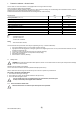
Insomeinstallations,whereparticularlyhighharmonicsoccur,thecurrentrunningonneutralmaybehigherthanthatofphases.
IntheLSIGrelease,thisprotectioncanbesetforthefollowingvalues:I
n
N=0-50%-100%-200%*I
n.
With three-pole circuit breakers, without external neutral, Neutral is adjusted to OFF
2.5.2 Guidance for Neutral adjustment
Adjustmentofneutralvalue(I
n
N)mustcomplywiththefollowingformula:I
1
xI
n
N≤Iu
Whena4-poleCBisavailable,thissettingiscontrolledbytherelaywhichsignalsthefaultthroughaLED(seepar.2.6.1),andautomatically
adjuststheparameterwithintheacceptedlimits.
Whena3-poleCBwithexternalneutralisavailable,therelaydoesnotperformanycontrolandsettingsaretobeadjustedbyuser.
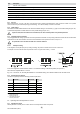
E.g.: With140G-N1200withRatingPlugat400A,Iu=1200AandI1=1In,adjustmentofI
n
Nmaybe50-100-200%
With140G-N1200and800ARatingPlug,Iu=1200AandI1=1In,adjustmentofI
n
Nmaybe50-100%
Note 1: I
1
=1l
n
setting is intended as the maximum adjustment of the protection against overloads. Actual maximum allowable adjustment must take into account any tempe-
rature derating, terminals used and altitude, or In (rating plug)≤ 50% of circuit breaker size.
Failure to comply with the setting limits for “I1“and“I
n
N” can cause damage to circuit breaker with consequent risks even for
operator.
2.5.3 Replacing an electronic release
TocompletetheprocedureforinstallingLSIG,takethefollowingsteps:
1. Withthecircuitbreakeropenandpreferablyisolated,installtheprotectionunitonthecircuitbreaker.
2. PowertheunitONLYfromthebatteryunit.
3. Iftherearenoerrorsotherthancongurationerror(seepar.2.6.1),pressandhold“iTest”buttonforafewsecondsuntilallredLEDs
startashingconrmingthatinstallationiscompleted.
4. Removethebatteryunit.
5. Powertherelayfromanysupply(Vaux,batteryunit).
6. Makesuretherearenocongurationerrors(“Alive”LEDglows).
7. Circuitbreakerandreleasecannowbecommissioned.
2.6 DenitionofalarmsandsignalsfortheLSIGunit
2.6.1 Optical signals
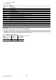
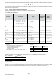
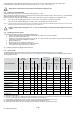
ThefollowingtableshowshowtheLEDsaremanagedinaccordancewithIEC60073standard(clause4.2.3.2inparticular).
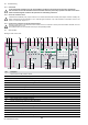
TheLEDalertsaboutstatusofthefunctionsetonitszone;e.g.inthegureinpar.2.5theLEDreferencedas8identiesstatusoffunctionL.
Alsoseethefollowingtable
LED permanently ON
TCerrororTCdisconnected
CSerrorordisconnected
RatingPlug/Installationerror
(1)
Protectiontimererror
Lasttrip
(2)
Testbutton presseda nd
nofailuredetected
(3)
Lpre-alarm
Congurationerror
(4)
Settingsinconsistency
Normaloperationofrelay
(5)
CBUndenedor
CBstatuserror
RED
Flashing
slowly (0.5 Hz)
RED
RED
RED
ORANGE
RED
RED
ORANGE
Type of information
All LEDs
All LEDs
All LEDs
All LEDs
Single LED
Single LED
Flashing fast (2Hz)
LED ashing with
two 0.5 sec pulses
every 2 sec
ORANGE
Single LED
LED ashing with
one pulse
every 3 sec
ORANGE
Single LED
LED permanently ON
Single LED
ORANGE
(1) RPdisconnectedorRP>Iu
(2) Informationonthe“Lasttrip”isdisplayedwhentheLEDrelatingtotheprotectionunitthathasbeentrippedcomeson.TheLEDremainson
for2sec,orpermanentlyifanoutsidepowersupply(frombatteryunit)isbeingused.
(3) TheinformationisdisplayedwithallLEDsonforaslongasthetestbuttonispressedandheld,orfor2sec.
(4) Installedvaluesdifferfromstoredvalues.Therefore,therelaymustbeinstalled(see2.5.3).
(5) Ifothersignalsaren’tpresent,theunit’soperatingmodeisindicated3secaftertheunithasbeenturnedon.