
User Manual

Publication 1408-UM001B-EN-P - May 2008 43
Appendix
A
Powermonitor 1000 Data Tables
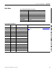
Summary of Data Tables
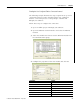
The Summary of Powermonitor 1000 Data Tables for all
Communication Protocols table summarizes all data tables available
and their general attributes
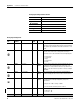
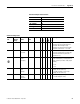
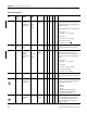
The rest of the tables detail each specific data table and its associated
elements, such as Modbus address, default value, ranges, and
description.
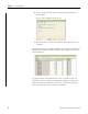
IMPORTANT
The lock symbol designates that the parameter that is
marked will not be able to be written when the hardware lock
terminals are connected together.
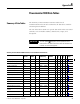
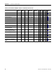
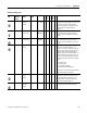
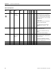
Summary of Powermonitor 1000 Data Tables for all Communication Protocols
Name of data table Data
Access
CSP
File No.
CIP Modbus
Addressing
No of
Elements
TR1
TR2
EM1
EM2
EM3
Refer to
Page
User Configured Table Results R F9 1 31601…31632 16 • 45
Analog Input Configuration RW F10 3 40001…40014 7 •••••46
Advanced Configuration RW F11 4 40101…40144 22 •••••47
RS485 Configuration RW N12 5 40201…40209 9 •••••51
Ethernet Configuration RW N13 6 40301…40323 23 •••••52
Time Zone Information 54
Date and Time Configuration RW N14 7 40401…40408 8 •••••57
Log Configuration RW N15 8 40501…40512 12 •••58
Command W F16 9 40601…40644 22 •••••61
Log Request RW N17 10 40701…40711 11 •••••64
Controller Interface W N18 11 40801…40808 8 ••66
Discrete Result R N19 12 30001…30006 6 •••••67
Wiring Diagnostics Results R F20 13 30101…30142 21 •••••68
Volts, Amps and Frequency
Results
R F21 14 30201…30232 16 •• •70
Power Results R F22 15 30301…30334 17 •• •71
Energy Results R F23 16 30401…30438 19 •••72